SX1231
ADVANCED COMMUNICATIONS & SENSING
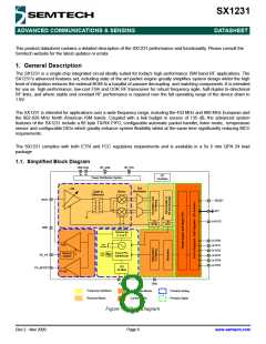
2.4. Chip Specification
DATASHEET
The tables below give the electrical specifications of the transceiver under the following conditions: Supply voltage VBAT1=
VBAT2=VDD=3.3 V, temperature = 25 °C, FXOSC = 32 MHz, F = 915 MHz, Pout = +13dBm, 2-level FSK modulation
RF
without pre-filtering, FDA = 5 kHz, Bit Rate = 4.8 kb/s and terminated in a matched 50 Ohm impedance, unless otherwise
specified.
Note Unless otherwise specified, the performances in the other frequency bands are similar or better.
2.4.1. Power Consumption
Table 4 Power Consumption Specification
Symbol
Description
Conditions
Min
Typ
Max
Unit
uA
IDDSL
IDDIDLE
IDDST
IDDFS
Supply current in Sleep mode
Supply current in Idle mode
Supply current in Standby mode
-
-
-
-
0.1
1.2
1.25
9
1
-
RC oscillator enabled
uA
Crystal oscillator enabled
1.5
-
mA
mA
Supply current in Synthesizer
mode
IDDR
IDDT
Supply current in Receive mode
-
16
-
mA
Supply current in Transmit mode
with appropriate matching, sta-
ble across VDD range
RFOP = +17 dBm, on PA_BOOST
RFOP = +13 dBm, on RFIO pin
RFOP = +10 dBm, on RFIO pin
RFOP = 0 dBm, on RFIO pin
RFOP = -1 dBm, on RFIO pin
-
-
-
-
-
95
45
33
20
16
-
-
-
-
-
mA
mA
mA
mA
mA
2.4.2. Frequency Synthesis
Table 5 Frequency Synthesizer Specification
Symbol
Description
Conditions
Min
Typ
Max
Unit
FR
Synthesizer Frequency Range
Programmable
290
424
862
-
-
-
340
510
1020
MHz
MHz
MHz
FXOSC
Crystal oscillator frequency
See section 7.1
-
-
32
-
MHz
us
TS_OSC
Crystal oscillator wake-up time
250
500
TS_FS
Frequency synthesizer wake-up
time to PllLock signal
From Standby mode
-
80
150
us
TS_HOP
Frequency synthesizer hop time
at most 10 kHz away from the
target
-
-
-
-
-
-
-
20
20
50
50
80
80
80
-
-
-
-
-
-
-
us
us
us
us
us
us
us
200 kHz step
1 MHz step
5 MHz step
7 MHz step
12 MHz step
20 MHz step
25 MHz step
FSTEP = FXOSC/219
Page 12
FSTEP
Frequency synthesizer step
-
61.0
-
Hz
Rev 2 - Nov 2009
www.semtech.com

 SEMTECH [ SEMTECH CORPORATION ]