Table 4-4: Output Signal Presence Indicator
Pre-Driver Output
OSP Pin
Valid signal present
0
1
No valid signal present
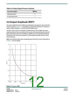
4.6 Output Amplitude (RSET)
The output amplitude of the GS2988 can be adjusted by changing the value of the RSET
resistor as shown in Figure 4-1. For an 800mV output with a nominal 7ꢀ tolerance, a
pp
value of 750Ω is required. A 1ꢀ SMT resistor should be used.
The RSET resistor is part of an internal DC feedback loop in the GS2988. The resistor
should be placed as close as possible to the R pin, and connected directly to the VCC
SET
plane (traces/wires may cause instability). In addition, the PCB capacitance should be
minimized at this node by removing the PCB groundplane beneath the RSET resistor
and the RSET pin.
Note: Care should be taken when considering layout of the RSET resistor. Please refer to
Section 5.1 for more details.
2.0
1.75
1.5
1.25
1.0
0.75
0.5
0.25
0.250
0.500
0.750
1.0
1.5
1.25
RSET (kΩ)
Figure 4-1: V
vs. RSET
OUT
GS2988
Final Data Sheet
12 of 18
Semtech
www.semtech.com
Rev.6
GENDOC-052131 July 2015

 SEMTECH [ SEMTECH CORPORATION ]