STK672-120-SL-E
• Thermal design
[Operating range in which a heat sink is not used]
The STK672-120-SL-E- package has a structure that uses no screws, and is recommended for use without a heat
sink .This section discusses the safe operating range when no heat sink is used.
In the maximum ratings specifications, Tc max is specified to be 105°C, and when mounted in an actual end product
system, the Tc max value must never be exceeded during operation. Tc can be expressed by formula (A) below, and
thus the range for ΔTc must be stipulated so that Tc is always under 105°C.
Tc = Ta + ΔTc (A)
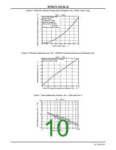
Ta: Hybrid IC ambient temperature, ΔTc: Temperature increase across the aluminum substrate
As shown in figure 6, the value of ΔTc increases as the hybrid IC internal average power dissipation PD increases.
As shown in figure 5, PD increases with the motor current. Here we describe the actual PD calculation using the
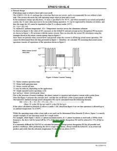
example shown in the motor current timing chart in figure 4.
Since there are periods when current flows and periods when the current is off during actual motor operation, PD
cannot be determined from the data presented in figure 5. Therefore, we calculate PD assuming that actual motor
operation consists of repetitions of the operation shown in figure 4.
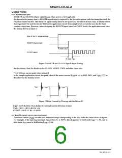
I 1
O
Motor phase current
(sink side)
I 2
O
-I 1
O
T1
T2
T0
T3
Figure 4 Motor Current Timing
T1: Motor rotation operation time
T2: Motor hold operation time
T3: Motor current off time
T2 may be reduced, depending on the application.
T0: Single repeated motor operating cycle
I 1 and I 2: Motor current peak values
O
O
Due to the structure of motor windings, the phase current is a positive and negative current with a pulse form.
Note that figure 4 presents the concepts here, and that the on/off duty of the actual signals will differ.
The hybrid IC internal average power dissipation PD can be calculated from the following formula.
PD = (T1 × P1 + T2 × P2 + T3 × 0) ÷ T0 ------------------------------------------- (I)
(Here, P1 is the PD for I 1 and P2 is the PD for I 2)
O
O
If the value calculated in formula (I) above is under 1.4W, then from figure 6 we see that operation is allowed up to
an ambient temperature Ta of 60°C.
While the operating range when a heat sink is not used can be determined from formula (I) above, figure 5 is merely
asingle example of one operating mode for a single motor.
For example, while figure 5 shows a 2-phase excitation motor, if 1-2 phase excitation is used with a 500Hz clock
frequency, the drive will be turned off for 25% of the time and the dissipation PD will be reduced to 75% of that in
figure 5.
It is extremely difficult for SANYO to calculate the internal average power dissipation PD for all possible end
product conditions. After performing the above rough calculations, always install the hybrid IC in an actual end
product and verify that the substrate temperature Tc does not rise above 105°C.
No. A2140-7/11

 SANYO [ SANYO SEMICON DEVICE ]