STK672-120-SL-E
Usage Notes
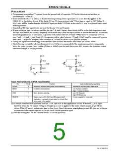
• 5V system input pins
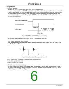
[RESETB and CLOCK 〈〈Input signal timing when power is first applied〉〉]
As shown in the timing chart, a RESETB signal input is required by the driver to operate with the timing in which the
F1 gate is turned on first. The RESETB signal timing must be set up to have a width of at least 20μs, as shown below.
The capacitor CO4 and the resistor RO3 in the application circuit form simple reset circuit that uses the RC time
constant rising time. However, when designing the RESETB input based on CMOS levels, the application must have
the timing shown in figure 2.
Rise of the 5V supply voltage
RESETB signal input
At least 20μs
CLOCK signal
At least 10μs
Figure 2 RESETB and CLOCK Signals Input Timing
See the timing chart for details on the CLOCK, MODE, CWB, and other input pins.
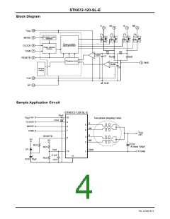
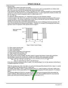
[Vref 〈〈Motor current peak value setting〉〉]
In the sample application circuit, the peak value of the motor current (I ) is set by RO1, RO2, and V
described by the formula below.
(5V) as
OH
DD
I
OH
0
Figure 3 Motor Current I Flowing into the Driver IC
O
I
= Vref÷Rs Here, Rs is hybrid IC internal current detection resistor
OH
Vref = (RO2÷ (RO1+RO2)) ×5V
STK672-120-SL-E: Rs = 0.165Ω
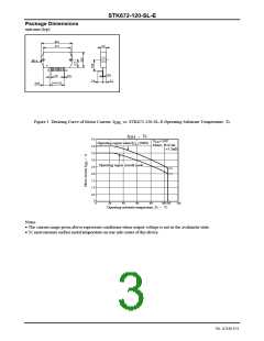
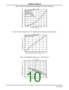
• Allowable motor current operating range
The motor current (I ) must be held within the range corresponding to the area under the curve shown in figure 1.
OH
For example, if the operating substrate temperature Tc is 105°C, then I
OH
must be held under I
= 2.4A, and in
OH
hold mode I
must be held under I
= 2.0A.
OH
OH
No. A2140-6/11

 SANYO [ SANYO SEMICON DEVICE ]