LC72121, 72121M, 72121V
Continued from preceding page.
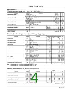
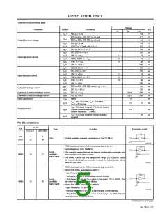
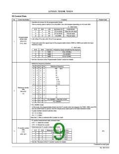
Ratings
typ
Parameter
Symbol
Conditions
Unit
min
max
1.0
V
OL1
OL2
PD: IO = 1 mA
V
BO1 to BO4, IO1, IO2: IO = 1 mA
BO1 to BO4, IO1, IO2: IO = 8 mA
DO: IO = 5 mA
0.2
1.6
1.0
0.5
5.0
5.0
8
V
V
Output low-level voltage
V
V
OL3
OL4
V
V
AOUT: IO = 1 mA, AIN = 1.3 V
CE, DI, CL: VI = 6.5 V
IO1, IO2: VI = 13 V
XIN: VI = VDD
V
I
IH1
IH2
µA
µA
µA
µA
µA
nA
µA
µA
µA
µA
µA
nA
µA
µA
nA
nA
pF
I
IIH3
1.3
Input high-level current
IIH4
IIH5
IIH6
FMIN, AMIN: VI = VDD
IFIN: VI = VDD
2.5
5.0
15
30
AIN: VI = 6.5 V
200
5.0
5.0
8
IIL1
IIL2
IIL3
IIL4
IIL5
IIL6
CE, DI, CL: VI = 0 V
IO1, IO2: VI = 0 V
XIN: VI = 0 V
1.3
2.5
5.0
Input low-level current
FMIN, AMIN: VI = 0 V
IFIN: VI = 0 V
15
30
AIN: VI = 0 V
200
5.0
5.0
200
200
IOFF1
BO1 to BO4, IO1, IO2, AOUT: VO = 13 V
DO: VO = 6.5 V
Output off leakage current
IOFF
2
High-level 3-state off leakage current
Low-level 3-state off leakage current
Input capacitance
IOFFH
IOFFL
CIN
PD: VO = VDD
0.01
0.01
6
PD: VO = 0 V
FMIN
VDD: Xtal = 7.2 MHz, fIN2 = 130 MHz,
IDD
IDD
IDD
1
2
3
2.5
0.3
6
mA
V
IN2 = 20 mVrms
V
DD: PLL block stopped (PLL inhibit mode)
Supply current
Crystal oscillator operating
(crystal frequency: 7.2 MHz)
mA
µA
VDD: PLL block stopped, crystal oscillator
stopped
10
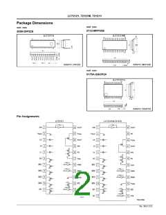
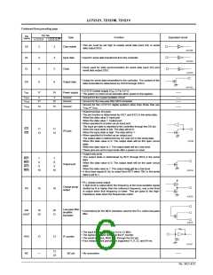
Pin Descriptions
Pin No.
Pin
Type
Function
Equivalent circuit
LC72121M
name
LC72121
LC72121V
XIN
1
1
Xtal
• Crystal oscillator element connections (4.5 or 7.2 MHz)
XOUT
22
24
• FMIN is selected when DVS in the serial data is set to 1.
• Input frequency: 10 to 160 MHz
Local
oscillator
signal input
• The signal is passed through an internal divide-by-two prescaler and
then input to the swallow counter.
FMIN
16
17
• The divisor can be set to a value in the range 272 to 65535. Since
the internal divide-by-two prescaler is used, the actual divisor will be
twice the set value.
• AMIN is selected when DVS in the serial data is set to 0.
• When SNS in the serial data is set to 1:
• Input frequency: 2 to 40 MHz
• The signal is input to the swallow counter directly.
Local
oscillator
signal input
• The divisor can be set to a value in the range 272 to 65535. The
set value becomes the actual divisor.
AMIN
15
16
• When SNS in the serial data is set to 0:
• Input frequency: 0.5 to 10 MHz
• The signal is input to a 12-bit programmable divider directly.
• The divisor can be set to a value in the range 4 to 4095. The set
value becomes the actual divisor.
Continued on next page.
No. 5815-5/22

 SANYO [ SANYO SEMICON DEVICE ]