LA6560
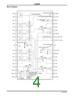
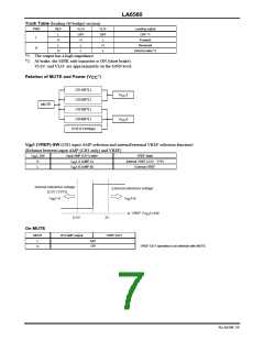
Truth Table (loading (H bridge) section)
FWD
REV
VLO+
VLO-
Loading output
L
H
L
OFF
H
OFF
L
OFF *1
Forward
L
L
H
Reversed
H
H
L
L
(Short) brake *2
*1 The output has a high impedance.
*2 At brake, the SINK side transistor is ON (short brake).
VLO+ and VLO- are approximately on the GND level.
Relation of MUTE and Power (V *)
CC
CH1(BTL)
V
V
1
2
CC
CH2(BTL)
MUTE
CH3(BTL)
CH4(BTL)
CC
CH5 (H bridge)
V
1 (VREF)-SW (CH1 input AMP selection and internal/external VREF selection function)
IN
(Relation between input AMP (CH1 only) and VREF)
V
1_SW
Input AMP (CH1) state
VREF state
IN
H
L
V
V
1-A (AMP-A)
1-B (AMP-B)
Internal VREF (2.5V : TYP)
External VREF
IN
IN
Internal reference voltage
(2.5V (TYP))
External reference voltage
V
1-A
IN
V
1-B
IN
VREF (V 1)-SW
IN
0.5V
2V
On MUTE
MUTE
BTLAMP output
VREF-OUT
L
OFF
ON
VREF-OUT operates in an interlock with MUTE.
H
No.A0599-7/9

 SANYO [ SANYO SEMICON DEVICE ]