S524A40X11/40X21/40X41/60X81/60X51 SERIAL EEPROM
BYTE WRITE OPERATION
DATA SHEET
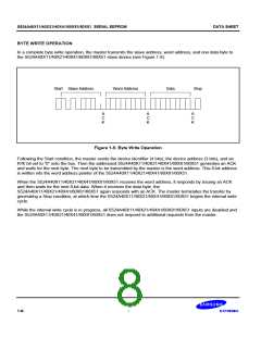
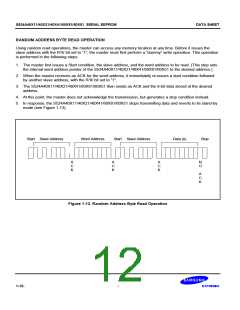
In a complete byte write operation, the master transmits the slave address, word address, and one data byte to
the S524A40X11/40X21/40X41/60X81/60X51 slave device (see Figure 1-9).
Start Slave Address
Word Address
Data
Stop
A
C
K
A
C
K
A
C
K
Figure 1-9. Byte Write Operation
Following the Start condition, the master sends the device identifier (4 bits), the device address (3 bits), and an
R/W bit set to “0” onto the bus. Then the addressed S524A40X11/40X21/40X41/60X81/60X51 generates an ACK
and waits for the next byte. The next byte to be transmitted by the master is the word address. This 8-bit address
is written into the word address pointer of the S524A40X11/40X21/40X41/60X81/60X51.
When the S524A40X11/40X21/40X41/60X81/60X51 receives the word address, it responds by issuing an ACK
and then waits for the next 8-bit data. When it receives the data byte, the
S524A40X11/40X21/40X41/60X81/60X51 again responds with an ACK. The master terminates the transfer by
generating a Stop condition, at which time the S524A40X11/40X21/40X41/60X81/60X51 begins the internal write
cycle.
While the internal write cycle is in progress, all S524A40X11/40X21/40X41/60X81/60X51 inputs are disabled and
the S524A40X11/40X21/40X41/60X81/60X51 does not respond to additional requests from the master.
1-8

 SAMSUNG [ SAMSUNG ]