PROGRAMMER'S MODEL
S3C4510B
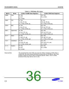
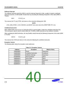
Table 2-1. PSR Mode. Bit Values
Visible THUMB State Registers
M[4:0]
10000
Mode
User
Visible ARM State Registers
R14..R0,
R7..R0,
LR, SP
PC, CPSR
PC, CPSR
10001
10010
10011
10111
11011
11111
FIQ
R7..R0,
R7..R0,
LR_fiq, SP_fiq
PC, CPSR, SPSR_fiq
R7..R0,
R14_fiq..R8_fiq,
PC, CPSR, SPSR_fiq
R12..R0,
IRQ
LR_irq, SP_irq
PC, CPSR, SPSR_irq
R7..R0,
R14_irq..R13_irq,
PC, CPSR, SPSR_irq
R12..R0,
Supervisor
Abort
LR_svc, SP_svc,
PC, CPSR, SPSR_svc
R7..R0,
R14_svc..R13_svc,
PC, CPSR, SPSR_svc
R12..R0,
LR_abt, SP_abt,
PC, CPSR, SPSR_abt
R7..R0
R14_abt..R13_abt,
PC, CPSR, SPSR_abt
R12..R0,
Undefined
System
LR_und, SP_und,
PC, CPSR, SPSR_und
R7..R0,
R14_und..R13_und,
PC, CPSR
R14..R0,
LR, SP
PC, CPSR
PC, CPSR
Reserved bits
The remaining bits in the PSRs are reserved. When changing a PSR¢s flag or
control bits, you must ensure that these unused bits are not altered. Also, your
program should not rely on them containing specific values, since in future
processors they may read as one or zero.
2-10

 SAMSUNG [ SAMSUNG ]