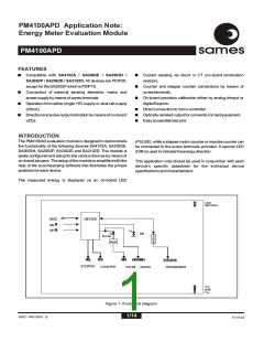
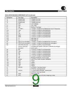
PM4100APD
ssaammeess
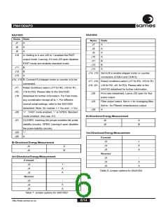
SETUP OF THE PM4100APD AS AN
ENERGY/POWER EVALUATION BOARD
The PM4100APD evaluation module comes with several
jumper selections, which allows the user to setup the module to
work for any of the devices mentioned. Tables 2 to 8 describe
the various jumper options. These tables should be used in
conjunction with figure 9, as well as the accompanying software
on disk (PM4100.exe) which will make it easier to locate the
jumper in question.
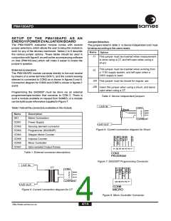
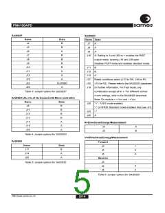
Jumper Selection
The jumpers listed in table 2 is device independent and must
be setup according to the users needs.
Name
Option
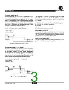
J1
This jumper must be inserted when measurement
is done using a CT, and left open when using a
shunt.
This jumper must be inserted when working from
J2
External connectors
a 110V supply system, and left open when a
220V supply is used.
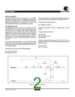
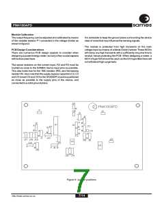
The PM4100APD module connects directly to live and neutral
by means of a screw terminal (SCK1), and the current sensing
element is connected to CON2 as is shown in figures 5 and 6.
Connection diagram for CON3 and CON6 is shown in figures 7
and 8.
J24
This jumper must be closed for regular use
J26
Insert this jumper when using a shunt, and leave
open when using a CT.
Programming the SA2002P must be done via an external
programmer/opto-isolator that connects to CON 3. There is
such a module available on request from SAMES, or a module
can be build as per information supplied in Figure 7.
Table 2: Device independent jumpers
LIVE IN
CON2
3
Table 1 lists all the connectors available on the module.
Shunt
2
1
Name
SK1
Description
Mains Connection
CURRENT
CON1
CON2
CON3
CON4
CON5
CON6
CON7
Power Supply
LIVE OUT
Sensing element connector
Programmer (SA2002P)
Stepper Motor Counter
Impulse Counter
Figure 6: Current connection diagram for Shunt
Micro Controller
Opto-isolated Output Pulses
Table 1: External connector descriptions
CON3
PROGRAM
Figure 7: SA2002P Programming Connector
LIVE IN
CT
CON2
3
2
1
CURRENT
LIVE OUT
Figure 5: Current connection diagram for CT
CON6
MICRO
Figure 8: Micro Controller Connector
4/14
http://www.sames.co.za

 SAMES [ SAMES ]