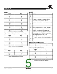
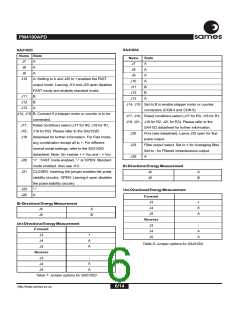
PM4100APD
ssaammeess
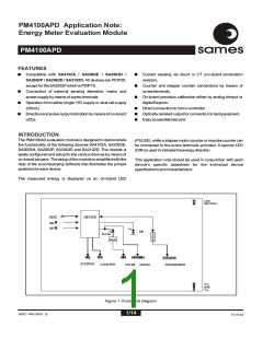
ANALOGINPUT
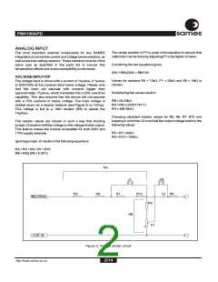
The center position of P1 is used in the equation to ensure that
calibrationcanbedonebyadjustingP1tobehigherorlower.
The most important external components for any SAMES
integrated circuit are the current and voltage sense resistors, as
well as the bias setting resistors. These resistors must be of the
same type as specified in the parts list to ensure that
temperatureeffectsandnoisesusceptibilityisminimized.
Combiningthetwoequationsgives:
(RA+RB)/220V=RB/14V
VOLTAGEINPUTIVP
Values for resistors R9 = 12kW, P1 = 20kW and R8 = 1MW is
The voltage input is driven with a current of 14µARMS (11µARMS
to SA4102A) at the nominal rated mains voltage. Please note
that this input will saturate with currents bigger than
approximately 17µARMS, which translates into a 20% overdrive
capability. This also ensures that the device will not saturate
with a 10% variance in mains voltage. The main voltage is
divided down via a resistor network (see Figure 2) to 14VRMS.
This voltage is fed to a 1MW resistor (R8) to realize the
14µARMS.
chosen.
Substitutingthevaluesresultin:
RB=26.29kW
RA=RBx(220V/14V-1)
RA=386.84kW
Choosing standard resistor values for R5, R6, R7, R10 and
keeping in mind that J2 must half the output voltage leads to the
followingvalues:
The resistor values are chosen in such a way that shorting
jumper J2 leads to half the voltage on the voltage divider output.
This feature makes the module compatible for both 220V and
110V supply networks.
R5=R7=82kW
R6=R10=100kW.
Ignoring jumper J2 results in the following equations:
RA = R5 + R6 + R7 + R10
RB = R8 || (R9 + 0.5P1)
RA
J2
J26
R5
R6
R7
R10
C1 R8
NEUTRAL
R9
RB
P1
LIVE IN
Figure 2: Voltage divider circuit
2/14
http://www.sames.co.za

 SAMES [ SAMES ]