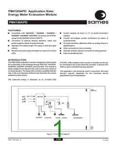
PM4100APD
ssaammeess
CURRENTSENSEINPUT
The capacitor C1 is inserted to compensate for the phase shift
caused by the current transformer. The following equation
shows how to calculate the capacitor value for a phase shift of
0.18degrees.
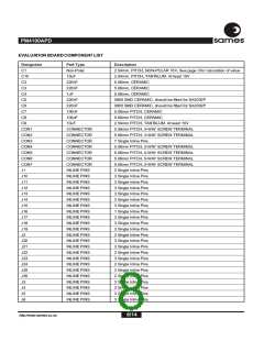
Resistors R2 and R3 (figure 3 and figure 4) define the current
level into the current sense inputs of the device. The
PM4100APD module can be configured to use any type of
shunt or CT, but to ensure proper current sensing it is advisable
to use a shunt or CT that will give a voltage drop of at least 20mV
at maximum supply current. The resistor values are calculated
for an input of 16µARMS on the current sense inputs at rated
conditions. Thedesignequationisasfollows:
C=1/(2x p xMainsfrequencyxR8xtan(Phaseshiftangle))
C=1/(2x p x50x1Mxtan(0.18degrees))
C=1.013µF
CTswithalowphaseisrecommended.
R2=R3=(IL /16µA)xRSH /2 SHUNT Sensing
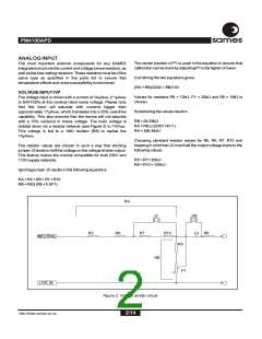
REFERENCE VOLTAGE
IL=Linecurrent
The on chip reference current is determined from a biasing
resistor R4 connected between pin 3 of the device and VSS.
This is 47kW for the SA2102D and SA4102A, and 24kW for the
restofthedevicescompatiblewiththismodule.
RSH =Shuntvalue
CON2
GND
3
2
1
ANALOGGROUND(GND)
R2
R3
CURRENT
IIN
IIP
The GND pin of the device is connected to the analog ground
plane, whichishalfwaybetweenVDD andVSS.
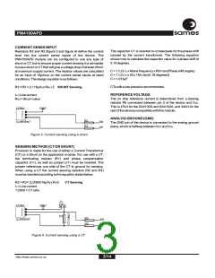
Figure 3: Current sensing using a shunt
SENSING METHOD (CT OR SHUNT)
Provision is made for the use of either a Current Transformer
(CT) or a Shunt on the application module. For use with a CT,
the terminating resistor (R1) and phase compensation
capacitor (C1), as well as jumper (J1) must be inserted. The
jumper references one side of the CT to ground for sensing.
When using a CT the current sensing resistors (R2 and R3)
mustbeinsertedaccordingtotheequationstatedbelow.
R2=R3=(I /2500/16µA)xR1/2
L
CT Sensing
IL=Linecurrent
1:2500=CTratio
J1
CT
CON2
GND
3
2
1
R1
R2
R3
CURRENT
IIN
IIP
Figure 4: Current sensing using a CT
3/14
http://www.sames.co.za

 SAMES [ SAMES ]