Daattaasshheeeett
BM2PXX2F
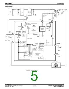
●Description of Blocks
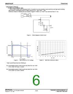
(1) Start circuit (DRIAN: 4pin)
This IC built in Start circuit (tolerates 650V). It enables to be low standby mode electricity and high speed starting.
After starting, consumption power is idling current ISTART3(typ=10uA) only.
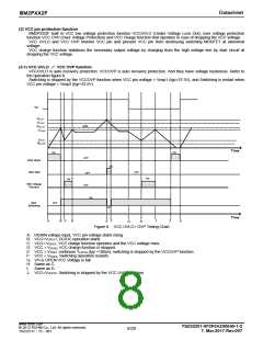
Reference values of Starting time are shown in figure-6. When Cvcc=10uF it can start less than 0.1 sec.
+
FUSE
AC
Diode
Bridge
85-265 Vac
-
DRAIN
SW1
VCC
Cvcc
+
-
VCCUVLO
Figure 4. Block diagram of start circuit
1.0
0.9
0.8
0.7
0.6
0.5
0.4
0.3
0.2
0.1
0.0
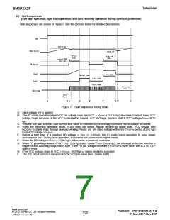
ISTART2
ISTART1
ISTART3
0
5
10
15
20
25
30
35
40
45
50
0
Vsc
VUVLO1
10V
VCC Voltage[V]
Cvcc [uF]
Figure 5. Start current vs VCC voltage
Figure 6. Start time (reference value)
* Start current flows from the DRAIN pin
Ex) Consumption power of start circuit only when the Vac=100V
PVH=100V*√2*10uA=1.41mW
Ex) Consumption power of start circuit only when the Vac=240V
PVH=240V*√2*10uA=3.38mW
www.rohm.com
TSZ02201-0F2F0A200040-1-2
7. Mar.2017.Rev.007
© 2012 ROHM Co., Ltd. All rights reserved.
6/20
TSZ22111・15・001

 ROHM [ ROHM ]