BD9415FS
3.2 External Components Selection
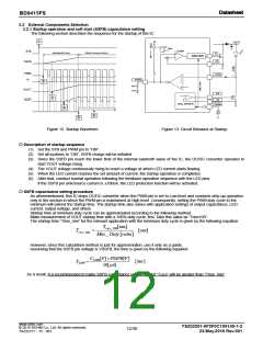
3.2.1 Startup operation and soft start (SSFB) capacitance setting
The following section describes the sequence for the startup of this IC.
①
5V
VOUT
Q
D
PWM
COMP
STB
Soft-Start(ISS=10uA)
IFB(Sink, Source)=±100uA)
N
DRIVER
OSC
OSC
CS
SSFB
PWM
N
LED_OK
LEDx
SSFB
②
RSSFB
CSSFB
VOUT
ILED
Gx
③
Sx
LED_ DRIVER
PWMx
④
LED_OK
⑥
⑤
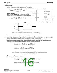
Figure 12. Startup Waveform
Figure 13. Circuit Behavior at Startup
Description of startup sequence
(1) Set the STB and PWM pin to “ON”.
(2) Set all systems to “ON”, SSFB charge will be initiated.
(3) Since the SSFB pin reach the lower limit of the internal sawtooth wave of the IC, the DC/DC converter operates to
start VOUT voltage rising.
(4) The VOUT voltage continuously rising to reach a voltage at which LED current starts flowing.
(5) When the LED current reaches the set amount of current, the startup operation is completed.
(6) After that, conduct normal operation following the feedback operation sequence with the LED pins.
If the SSFB pin sink/source current is ±100uA, the LED protection function will be activated.
SSFB capacitance setting procedure
As aforementioned, this IC stops DC/DC converter when the PWM pin is set to Low level and conducts step-up operation
only in the section in which the PWM pin is maintained at High level. Consequently, setting the PWM duty cycle to the
minimum will extend the startup time. The startup time also varies with application settings of output capacitance, LED
current, output voltage, and others.
Startup time at minimum duty cycle can be approximated according to the following method:
Make measurement of VOUT startup time with a 100% duty cycle, first. Take this value as “Trise100”.
The startup time “Trise_min” for the relevant application with the minimum duty cycle is given by the following equation.
Trise_100[sec]
Trise_ min
[sec]
Min _ Duty [ratio]
However, since this calculation method is just for approximation, use it only as a guide.
Assuming that the SSFB pin voltage is VSSFB, the time is given by the following equation:
CSSFB[F]VSSFB[V]
TSSFB
[Sec]
10[A]
As a result, it is recommended to make SSFB capacitance setting so that “TSSFB” will be greater than “Trise_min”
www.rohm.com
TSZ02201-0F2F0C100140-1-2
23.May.2016 Rev.001
© 2015 ROHM Co., Ltd. All rights reserved.
12/30
TSZ22111・15・001

 ROHM [ ROHM ]