BD9109FVM-LB
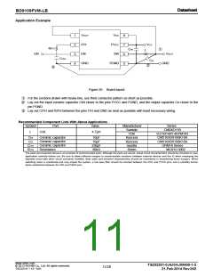
Selection of Components Externally Connected
1. Selection of inductor (L)
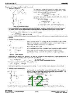
The inductance significantly depends on output ripple current.
As seen in the equation (1), the ripple current decreases as the
inductor and/or switching frequency increases.
IL
ΔIL
(VCC-VOUT)×VOUT
VCC
ΔIL=
[A]・・・(1)
L×VCC×f
Appropriate ripple current at output should be 30% more or less of
the maximum output current.
IL
VOUT
ΔIL=0.3×IOUTmax[A]・・・(2)
L
(VCC-VOUT)×VOUT
Co
L=
[H]・・・(3)
ΔIL×VCC×f
(ΔIL: Output ripple current, and f: Switching frequency)
Figure 27. Output ripple current
Current exceeding the current rating of the inductor results in magnetic saturation of the inductor, which decreases efficiency.
The inductor must be selected allowing sufficient margin with which the peak current may not exceed its current rating.
If VCC=5V, VOUT=3.3V, f=1MHz, ΔIL=0.3×0.8A=0.24A, for example,
(5-3.3)×3.3
L=
=4.675μ → 4.7[μH]
0.24×5×1M
Select the inductor of low resistance component (such as DCR and ACR) to minimize dissipation in the inductor for better
efficiency.
2. Selection of output capacitor (CO)
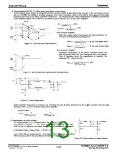
VCC
Output capacitor should be selected with the consideration on the stability
region and the equivalent series resistance required to smooth ripple voltage.
Output ripple voltage is determined by the equation (4):
ΔVOUT=ΔIL×ESR [V]・・・(4)
VOUT
L
(ΔIL: Output ripple current, ESR: Equivalent series resistance of output capacitor)
ESR
Co
*Rating of the capacitor should be determined allowing sufficient margin
against output voltage. Less ESR allows reduction in output ripple voltage.
Figure 28. Output capacitor
As the output rise time must be designed to fall within the soft-start time, the capacitance of output capacitor should be
determined with consideration on the requirements of equation (5):
Tss: Soft-start time
Ilimit: Over current detection level, 2A(Typ)
TSS×(Ilimit-IOUT)
Co≦
[F]・・・(5)
VOUT
For instance, and if VOUT=3.3V, IOUT=0.8A, and TSS=1ms,
1m×(2-0.8)
Co≦
≒364 [μF]
3.3
Inappropriate capacitance may cause problem in startup. A 10 μF to 100 μF ceramic capacitor is recommended.
3. Selection of input capacitor (Cin)
Input capacitor to select must be a low ESR capacitor of the capacitance
VCC
sufficient to cope with high ripple current to prevent high transient voltage. The
Cin
ripple current IRMS is given by the equation (6):
√
VOUT(VCC-VOUT)
VOUT
IRMS=IOUT×
[A]・・・(6)
VCC
L
Co
< Worst case > IRMS(max)
IOUT
When VCC is twice the Vout, IRMS=
2
If VCC=5V, VOUT=3.3V, and IOUTmax=0.8A,
√
Figure 29. Input capacitor
3.3(5-3.3)
IRMS=0.8×
=0.38[ARMS]
5
A low ESR 10μF/10V ceramic capacitor is recommended to reduce ESR dissipation of input capacitor for better efficiency.
www.rohm.com
TSZ02201-0J4J0AJ00600-1-2
21.Feb.2014 Rev.002
© 2013 ROHM Co., Ltd. All rights reserved.
12/20
TSZ22111 • 15 • 001

 ROHM [ ROHM ]