RT8859M
influences the pulse width of quick response. A voltage
divider circuit is recommended to be applied to the
QRSETA pin. Therefore, with a little modification of
equation (49), the pulse width of quick response pulse
can be calculated as :
the over current condition is not valid for 15 continuous
cycles, the OCP latch counter will be reset. When OCP
is triggered by the AXGVR, the CORE VR will also enter
soft shut down sequence.
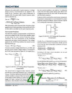
If inductorDCR is used as the current sense component,
temperature compensation is recommended for proper
protection under all conditions. Figure 25 shows a typical
OCP setting with temperature compensation.
VQRSETA
1.2
20.33 x 10⁻¹² x RTON x VQRSETA
tON, QR
=
x tON
(62)
=
VIN − VDAC, AXG
V
CC
After generating a quick response pulse, the pulse is then
applied to the on-time generation circuit and theAXGVR's
on-time will be overridden by the quick response pulse.
R
OC1a
NTC
OC1b
OC2
R
OCSETA
Over Current Protection
R
The AXGVR compares a programmable current limit set
point to the voltage from the current sense amplifier output
of each phase for Over Current Protection (OCP).
Therefore, the OCP mechanism of the RT8859M
implements per-phase current protections. The voltage
applied to the OCSETA pin defines the desired current
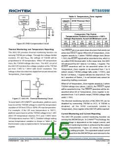
Figure 25. AXGVR : OCP Setting with Temperature
Compensation
Usually, ROC1a is Selected to be equal to the thermistor's
nominal resistance at room temperature. Ideally, assume
VOCSET has the same temperature coefficient as RSENSE
(InductorDCR) :
limit threshold ILIMIT
:
VOCSETA = 48 x ILIMIT x RSENSE
(63)
V
R
SENSE, HOT
OCSETA, HOT
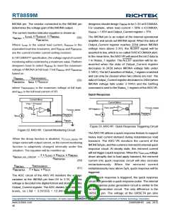
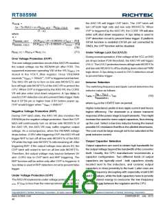
Connect a resistive voltage divider from VCC toGND, and
the joint of the resistive voltage divider is connected to
=
(64)
V
R
SENSE, COLD
OCSETA, COLD
the OCSETApin as shown in Figure 24. For a given ROC2
,
According to the basic circuit calculation, we can get
VOCSETA at any temperature :
V
⎛
⎞
CC
R
= R
x
OC2
−1
⎟
OC1
⎜
⎝
V
OCSET
⎠
VOCSETA, T°C
=
V
CC
ROC2
ROC1a / /RNTC, 25°C + ROC1b + ROC2
VCC
x
(65)
R
OC1
OCSETA
Re-write (64) from (65) to get VOCSETA at room temperature:
R
OC2
R
//R
+ R
+ R
+ R
+ R
R
SENSE, HOT
OC1a
NTC, COLD
OC1b
OC2
=
R
//R
R
SENSE, COLD
OC1a
NTC, HOT
OC1b
OC2
(66)
Figure 24. AXGVR : OCP Setting without Temperature
Compensation
VOCSETA, 25°C
=
ROC2
ROC1a / /RNTC, 25°C + ROC1b + ROC2
VCC
x
(67)
(68)
The current limit is triggered when inductor current
exceeds the current limit threshold, ILIMIT, as defined by
VOCSETA. The driver will then be forced to turn off UGATE
until the condition is cleared. If the over current condition
of any phase remains valid for 15 cycles, theAXGVR will
trigger OCP latch. Latched OCP forces PWM into high
impedance, which disables internal PWM logic drivers. If
Solving (66) and (67) yields ROC1b and ROC2
ROC2
=
α ×REQU, HOT −REQU, COLD + (1− α)×REQU, 25°C
VCC
×(1− α)
VOCSETA, 25°C
Copyright 2012 Richtek Technology Corporation. All rights reserved.
©
is a registered trademark of Richtek Technology Corporation.
DS8859M-05 July 2012
www.richtek.com
47

 RICHTEK [ RICHTEK TECHNOLOGY CORPORATION ]