ib technology
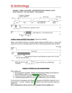
Example c) Mifare card in field, valid READ BLOCK command received
(Read cmd (0x52) + Keycode number + Block number)
Command + parameters
received + 6mS CTS
TTL levels
5v
Not to scale
CTS
0v
100 ms polling delay
(card still present)
Polling cycle
repeats
6ms
9ms
37ms
1
5v
0v
RWD
RX
2
(3ms) Command byte + parameters received
5v
0v
RWD
TX
3
Acknowledge byte + 16 byte block data reply
20ms
17ms
Auxiliary output and BEEP delay timing (if options are enabled)
Mifare card in field for first time, Auxiliary output enabled and BEEP delay set. Green LED
signal can be used as an interrupt signal to the host to indicate that auxiliary data will follow.
TTL levels
5v
GREEN
LED
0v
5v
Not to scale
AUX
OUT
0v
Representation of Auxiliary (serial/Wiegand) data output on OP0 / OP1 pins
2mS after Green LED signal
5v
0v
CTS
BEEP delay after Aux output
(if enabled)
CTS goes LOW after Aux out/BEEP delay
Summary of Polling rates and command timing
Three polling rates:
1) NO card and NO commands: Polling rate determined by Polling rate parameter in
RWD EEPROM (4mS to 8 seconds, default setting 260mS)
2) Card present but NO commands: 100ms polling delay between CTS pulses.
3) Command (and parameters) received: 10ms polling delay to next CTS pulse.
For lowest power consumption, the Polling rate parameter in EEPROM is typically set to a
long period (> 1 second). Auxiliary output (if enabled) occurs after Green LED signal and
before CTS.
Host communication software must be able to handle the three polling rates.
7

 RFSOLUTIONS [ RFSOLUTIONS.LTD ]