ib technology
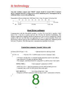
The CTS line remains in a LOW state while the command and data bytes are being received.
After the last byte of data the CTS signal “times out” for 6ms and returns HIGH.
This 6ms “window” every polling cycle allows the host computer to send a single command
and associated data to the RWD. Please note that only one command and it’s corresponding
data bytes can be sent during a CTS LOW period, the command and data bytes must be sent
with no gaps between, if there is a pause of more than 6ms between bytes then “time out”
occurs, the CTS line returns high and the command fails (flagged as RS232 error). The CTS
signal idles in this HIGH state (to inhibit host communication) until the next polling cycle
begins.
The communication baud rate is 9600 baud, 8 bits, 1 stop, no parity. The RWD Tx, Rx and
CTS signals are all TTL level and can be converted to +/-10v RS232 levels using a level
converter device such as the MAX202 (note the inversion of the TTL levels).
The Micro RWD MF LP (low-power) version has been specifically designed to operate
with very low average power consumption but still remain responsive to cards entering
and leaving the field and be able to read large amounts of data as quickly as possible.
THE RWD HAS THREE POLLING STATES:
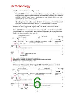
1) NO card present and NO host commands received.
Polling cycle rate (time between subsequent CTS low periods) is determined by the
“polling rate” parameter stored in the RWD EEPROM memory. This is typically set
to a long period (4ms to 8 seconds, default setting 260mS) and is the primary means to
reduce average power consumption. This is because most of the polling cycle period is
spent in a power-down/sleep mode.
Not to scale
TTL levels
5v
CTS
0v
Polling cycle
repeats
6ms
(CTS timeout)
Polling cycle period set by RWD EEPROM
parameter (4ms to 8 seconds, default 1 second)
RF ON for brief period
(to check for card)
RF OFF, Power-down/sleep period
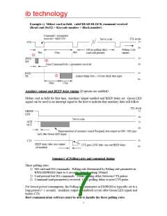
2) Mifare card in field, NO host commands received.
When a card is detected in the field the polling rate changes to approximately 100ms
(between CTS low periods). This is to ensure that the RWD can respond quickly to the
card leaving the field and a new card being presented.
TTL levels
5v
Not to scale
CTS
0v
100ms polling rate
6ms (CTS timeout)
100ms polling rate
Polling cycle
repeats
RF ON for brief period (to check for card)
5
RF OFF, Power-down/sleep period

 RFSOLUTIONS [ RFSOLUTIONS.LTD ]