ib technology
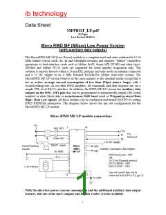
The MicroRWD MF LP is a proximity system and a Read/Write range of up to 10cm can be
achieved under ideal conditions using the appropriate antenna. For evaluation purposes the
RWD is available on a base board with PCB antenna, LEDs, power-regulation, 9-pin RS232
and optional USB interfaces. When power is first applied to the board the red and green LEDs
flash once to indicate successful power-up (both LEDs stay on if initialisation fails). The
RWD can also check for antenna faults and internal error conditions, these problems are
indicated by the red LED or both LEDs flashing continuously until the fault has been
rectified.
The RWD will normally have the red LED lit until a valid card is brought into the RF field. If
the tag is accepted as valid then the green LED is turned ON (and red LED OFF). If the
auxiliary output features are enabled then the UID (serial number) is acquired, or block data is
internally read and transmitted as serial data or Wiegand protocol data on OP0/OP1 pins.
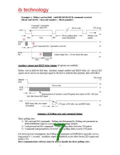
If the Beep delay is set then the “BEEP” output (pin 4) is pulsed ON/OFF. With auxiliary
output features turned OFF, the RWD responds to host commands on the TTL serial interface
at 9600 baud, 8 bits, 1 stop, no parity, as usual.
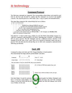
Note: Some ISO14443A compliant cards have a SINGLE (4 byte) UID and others have a
DOUBLE (7 byte) UID. These serial numbers are acquired as part of the initial
anticollision/select procedure when a card is brought into the field. This UID information can
be reported using the CARD UID command. For Mifare Classic 1k and 4k cards the SINGLE
UID is acquired and can be reported BUT subsequent block read/write operations will not
function if the Security KEY is incorrect for the particular sector and the authentication fails.
For many applications where only the UID (serial number) is required, the Security KEY
information is therefore NOT required.
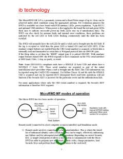
MicroRWD MF modes of operation
The Micro RWD has two basic modes of operation:-
Micro RWD
Chip Module
Micro RWD
Chip Module
Standalone mode with
Internal EEPROM holding
authorised Mifare serial
numbers for acceptance
RS232
Serial
comms
Antenna
Antenna
Host System
Remote mode (connected to a host computer or microcontroller) and Standalone mode.
1) Remote mode involves connecting to a host serial interface. This is where the stored
list of authorised identity codes (serial numbers) can be empty, effectively authorising
any Mifare card for subsequent read/write operations (depending on correct Security
Key. A simple serial protocol allows a host system to communicate with the Micro
RWD in order to program new authorised identity codes, change parameters, load
Security Keys and perform Read/Write operations to the card itself.
3

 RFSOLUTIONS [ RFSOLUTIONS.LTD ]