R8C/13 Group
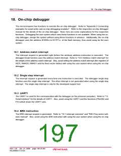
17.5 Standard Serial I/O Mode
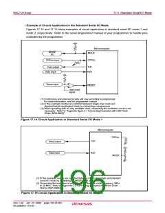
• Example of Circuit Application in the Standard Serial I/O Mode
Figures 17.14 and 17.15 show examples of circuit application in standard serial I/O mode 1 and
mode 2, respectively. Refer to the serial programmer manual of your programmer to handle pins
controlled by the programmer.
Microcomputer
MODE
MODE
I/O
CNVss
CNVss input
TxD
RxD
Data output
Data input
Reset input
RESET
User reset
signal
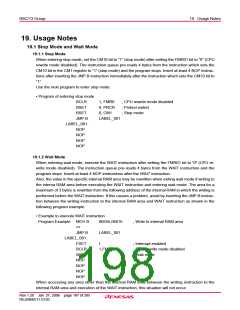
(1) Control pins and external circuitry will vary according to programmer.
For more information, see the programmer manual.
(2) In this example, modes are switched between single-chip mode and
standard serial input/output mode by connecting a programmer.
(3) When operating with on-chip oscillator clock, connecting the oscillation circuit is not
necessary. Refer to "Appendix figure 2.1 Connecting Examples with USB Flash
Writer (M3A-0665)".
Figure 17.14 Circuit Application in Standard Serial I/O Mode 1
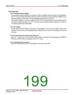
Microcomputer
CNVss
TxD
RxD
Data output
Data input
MODE
(1) In this example, modes are switched between single-chip mode and standard
serial I/O mode by controlling the MODE input with a switch.
(2) Connecting the oscillation is necessary. Set the main clock frequency 1MHz
to 20 MHz. Refer to "Appendix 2.2 Connecting examples with M16C Flash
Starter (M3A-0806)".
Figure 17.15 Circuit Application in Standard Serial I/O Mode 2
Rev.1.20 Jan 27, 2006 page 185 of 205
REJ09B0111-0120

 RENESAS [ RENESAS TECHNOLOGY CORP ]