R8C/13 Group
19. Usage Notes
19.2.5 Changing Interrupt Factor
The IR bit in the interrupt control register may be set to “1” (interrupt requested) when the interrupt
factor is changed. When using an interrupt, set the IR bit to “0” (interrupt not request) after changing
the interrupt factor. In addition, the changes of interrupt factors include all elements that change the
interrupt factors assigned to individual software interrupt numbers, polarities, and timing. Therefore,
when a mode change of the peripheral functions involves interrupt factors, edge polarities, and timing,
set the IR bit to “0” (interrupt not requested) after the change. Refer to each peripheral function for the
interrupts caused by the peripheral functions.
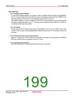
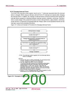
Figure 19.1 shows an Example of Procedure for Changing Interrupt Factor.
Interrupt factor change
Disable Interrupt(2, 3)
Change interrupt factor (including mode of
peripheral functions)
Set IR bit to “0” (interrupt not requested) using
MOV instruction(3)
Enable interrupt(2, 3)
Change completed
• IR bit: The interrupt control register bit of an interrupt whose
factor is changed
NOTES:
1. Execute the above setting individually. Do not execute two
or more settings at once (by one instruction).
2. Use the I flag for the INTi (i=0 to 3) interrupt.
To prevent interrupt requests from being generated when
using peripheral function interrupts other than the INTi
interrupt factor. In this case, use the I flag when all
maskable interrupts can be disabled. When all maskable
interrupts cannot be disabled, use the ILVL0 to ILVL2 bits
of the interrupt whose factor is changed.
3. Refer to “19.2.6 Changing Interrupt Control Register” for the
instructions to be used and their usage notes.
Figure 19.1 Example of Procedure for Changing Interrupt Factor
Rev.1.20 Jan 27, 2006 page 189 of 205
REJ09B0111-0120

 RENESAS [ RENESAS TECHNOLOGY CORP ]