R8C/13 Group
Table 16.6 Voltage Detection Circuit Electrical Characteristics
16. Electrical Characteristics
Standard
Unit
Symbol
Vdet
Parameter
Measuring condition
Min.
3.3
Typ.
3.8
Max.
4.3
Voltage detection level
V
(
µs
40
Voltage detection interrupt request generating time 2)
Voltage detection circuit self consumption current
VC27=1, VCC=5.0V
600
nA
µs
V
(
td(E-A)
20
Waiting time until voltage detection circuit operation starts 3)
Microcomputer operation voltage minimum value
2.7
Vccmin
NOTES:
1. The measuring condition is Vcc=AVcc=2.7V to 5.5V and Topr=-40°C to 85°C.
2. This shows the time until the voltage detection interrupt request is generated since the voltage passes Vdet.
3. This shows the required time until the voltage detection circuit operates when setting to "1" again after setting the VC27 bit in the VCR2
register to “0”.
(1, 3)
Table 16.7 Reset Circuit Electrical Characteristics (When Using Hardware Reset 2
)
Standard
Typ.
Symbol
Vpor2
Measuring condition
Parameter
Unit
Min.
Max.
Vdet
Power-on reset valid voltage
–20°C ≤ Topr < 85°C
–20°C ≤ Topr < 85°C, t
V
t
W
(Vpor2-
Vdet)
(2)
Supply voltage rising time when power-on reset is canceled
(4)
ms
100
W
(por2) ≥ 0s
NOTES:
1. The voltage detection circuit which is embedded in a microcomputer is a factor to generate the hardware reset 2. Refer to 5.1.2 Hardware
Reset 2.
2. This condition is not applicable when using VCC
≥ 1.0V.
3. When turning power on after the external power has been held below the valid voltage (Vpor1) for greater than 10 seconds, refer to Table 16.8
Reset Circuit Electrical Characteristics (When Not Using Hardware Reset 2).
4. tw(por2) is time to hold the external power below effective voltage (Vpor2).
Table 16.8 Reset Circuit Electrical Characteristics (When Not Using Hardware Reset 2)
Standard
Typ.
Measuring condition
Symbol
Parameter
Unit
V
Min.
Max.
0.1
Vpor1
Power-on reset valid voltage
–20°C
0°C
≤
Topr < 85°C
tW(Vpor1-
Vdet)
Supply voltage rising time when power-on reset is canceled
Supply voltage rising time when power-on reset is canceled
100
100
ms
≤
Topr ≤ 85°C, tW(por1) ≥ 10s(2)
tW(Vpor1-
Vdet)
30s(2)
10s(2)
ms
–20°C
–20°C
≤
≤
Topr < 0°C, t
Topr < 0°C, t
W
(por1)
(por1)
≥
tW(Vpor1-
Vdet)
Supply voltage rising time when power-on reset is canceled
Supply voltage rising time when power-on reset is canceled
1
ms
ms
W
≥
tW(Vpor1-
Vdet)
(por1) ≥ 1s(2)
0.5
0°C
≤
Topr
≤
85°C, t
W
NOTES:
1. When not using hardware reset 2, use with Vcc
≥ 2.7V.
2. tw(por1) is time to hold the external power below effective voltage (Vpor1).
(3)
det
(3)
det
V
V
V
V
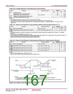
cc min
por2
Vpor1
(1,2)
Sampling time
tw(por2)
tw(Vpor2 –Vdet)
t
w(por1) tw(Vpor1–Vdet)
Internal reset signal
(“L” effective)
1
1
X 32
X 32
f
RING-S
f
RING-S
NOTES:
1. Hold the voltage of the microcomputer operation voltage range (Vccmin or above) within sampling time.
2. A sampling clock is selectable. Refer to “5.4 Voltage Detection Circuit” for details.
3. Vdet shows the voltage detection level of the voltage detection circuit. Refer to “5.4 Voltage Detection Circuit” for details.
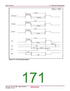
Figure 16.3 Reset Circuit Electrical Characteristics
Rev.1.20 Jan 27, 2006 page 156 of 205
REJ09B0111-0120

 RENESAS [ RENESAS TECHNOLOGY CORP ]