R8C/13 Group
16. Electrical Characteristics
16. Electrical Characteristics
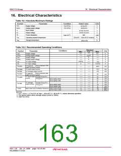
Table 16.1 Absolute Maximum Ratings
Symbol
Parameter
Condition
Rated value
Unit
V
V
CC
Supply voltage
V
CC=AVCC
-0.3 to 6.5
-0.3 to 6.5
V
VCC=AVCC
AVCC
Analog supply voltage
Input voltage
VI
V
V
-0.3 to VCC+0.3
-0.3 to VCC+0.3
Output voltage
VO
P
d
Power dissipation
C
300
Topr=25
mW
C
T
opr
Operating ambient temperature
Storage temperature
-20 to 85 / -40 to 85 (D version)
T
stg
C
-65 to 150
Table 16.2 Recommended Operating Conditions
Standard
Typ.
Conditions
Symbol
Parameter
Unit
Min.
Max.
VCC
Supply voltage
2.7
5.5
V
(3)
AVcc
Vss
Analog supply voltage
Supply voltage
V
CC
V
V
V
0
AVss
Analog supply voltage
"H" input voltage
0
0.8VCC
0
V
V
V
IH
IL
VCC
0.2VCC
-60.0
V
"L" input voltage
Sum of all pins' IOH
(peak)
"H" peak all
output currents
IOH (sum)
mA
IOH (peak)
IOH (avg)
IOL (sum)
"H" peak output current
-10.0
-5.0
mA
mA
"H" average output current
Sum of all pins' IOL
"L" peak all
60
mA
(peak)
output currents
"L" peak output
current
Except P10 to P17
10
30
mA
mA
mA
mA
IOL (peak)
P10 to P17
Drive ability HIGH
Drive ability LOW
10
5
"L" average
output current
Except P1
P1 to P1
0 to P17
IOL (avg)
Drive ability HIGH
Drive ability LOW
3.0V ≤ Vcc ≤ 5.5V
2.7V ≤ Vcc < 3.0V
mA
mA
MHz
MHz
15
0
7
5
20
10
0
0
f (XIN
)
Main clock input oscillation frequency
NOTES:
1. VCC = AVCC = 2.7 to 5.5V at Topr = -20 to 85 °C / -40 to 85 °C, unless otherwise specified.
2. The typical values when average output current is 100ms.
3. Hold Vcc=AVcc.
Rev.1.20 Jan 27, 2006 page 152 of 205
REJ09B0111-0120

 RENESAS [ RENESAS TECHNOLOGY CORP ]