R8C/13 Group
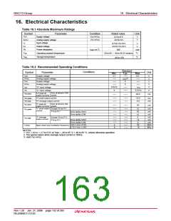
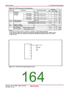
Table 16.3 A/D Conversion Characteristics
16. Electrical Characteristics
Standard
Unit
Symbol
Parameter
Measuring condition
Min. Typ. Max.
–
–
Resolution
V
ref =VCC
10
Bit
Absolute
accuracy
øAD=10 MHz, Vref=Vcc=5.0V
øAD=10 MHz, Vref=Vcc=5.0V
10 bit mode
8 bit mode
LSB
LSB
LSB
±3
±2
øAD=10 MHz, Vref=Vcc=3.3V(3)
øAD=10 MHz, Vref=Vcc=3.3V(3)
±5
10 bit mode
8 bit mode
±2
40
LSB
kΩ
V
REF=VCC
R
LADDER
Ladder resistance
Conversion time
10
µs
µs
V
t
CONV
øAD=10 MHz, Vref=Vcc=5.0V
øAD=10 MHz, Vref=Vcc=5.0V
3.3
2.8
10 bit mode
8 bit mode
(4)
CC
Reference voltage
V
REF
IA
V
Analog input voltage
V
0
V
ref
V
A/D operating
clock frequency(2)
0.25
1.0
Without sample & hold
With sample & hold
MHz
MHz
10
10
–
NOTES:
1. VCC=AVCC=2.7 to 5.5V at Topr = -20 to 85 °C / -40 to 85 °C, unless otherwise specified.
2. If fAD exceeds 10 MHz more, divide the fAD and hold A/D operating clock frequency (ØAD) 10 MHz or below.
3. If the AVcc is less than 4.2V, divide the fAD and hold A/D operating clock frequency (ØAD) fAD/2 or below.
4. Hold Vcc=Vref.
P0
30pF
P1
P2
P3
P4
Figure 16.1 Port P0 to P4 measurement circuit
Rev.1.20 Jan 27, 2006 page 153 of 205
REJ09B0111-0120

 RENESAS [ RENESAS TECHNOLOGY CORP ]