M51995AP/AFP
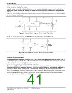
Driver Circuit for Bipolar Transistor
When the bipolar transistor is used instead of MOS FET, the base current of bipolar transistor must be sinked by the
negative base voltage source for the switching-off duration, in order to make the switching speed of bipolar transistor
fast one.
In this case, over current can not be detected by detecting resistor in series to bipolar transistor, so it is recommended to
use the CT (current transformer).
VCC
VCC
Collector
M51995A
Emitter
VOUT
−VSS
(−2 V to −5 V)
GND
Figure 45 Driver Circuit Diagram (1) for Bipolar Transistor
For the low current rating transistor, type M51995A can drive it directly as shown in figure 46.
VCC
Collector
M51995A
VOUT
Bipolar
transistor
GND
Emitter
Figure 46 Driver Circuit Diagram (2) for Bipolar Transistor
Attention for Heat Generation
The maximum ambient temperature of type M51995A is +85°C, however, the ambient temperature in vicinity of the IC
is not uniform and varies place by place, as the amount of power dissipation is fearfully large and the power dissipation
is generated locally in the switching regulator.
So it is one of the good idea to check the IC package temperature.
The temperature difference between IC junction and the surface of IC package is 15°C or less, when the IC junction
temperature is measured by temperature dependency of forward voltage of pin junction, and IC package temperature is
measured by “thermo-viewer”, and also the IC is mounted on the “phenol-base” PC board in normal atmosphere.
So it is concluded that the maximum case temperature (surface temperature of IC) rating is 120°C with adequate margin.
As type M51995 has the modified totempole driver circuit, the transient through current is very small and the total
power dissipation is decreased to the reasonable power level.
REJ03D0835-0300 Rev.3.00 Jun 06, 2008
Page 39 of 40

 RENESAS [ RENESAS TECHNOLOGY CORP ]