MITSUBISHI MICROCOMPUTERS
M37754M8C-XXXGP, M37754M8C-XXXHP
M37754S4CGP, M37754S4CHP
SINGLE-CHIP 16-BIT CMOS MICROCOMPUTER
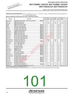
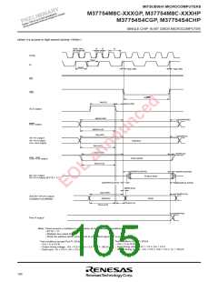
Switching characteristics (VCC = 5 V±10 %, VSS = 0 V, Ta = –20 to 85 °C, f(XIN) = 40 MHz when the clock source select bit =
“0” , unless otherwise noted)
Memory expansion and Microprocessor mode : High-speed running
3-φ access
4−φ access
5-φ access
Symbol
Parameter
Unit
Min. Max. Min. Max. Min. Max.
tw(φH), tw(φL)
td(φ1–WR)
φ high-level pulse width, φ low-level pulse width
(Note)
5
5
5
–7
–7
130
130
45
45
35
45
45
35
45
45
35
ns
ns
ns
ns
ns
ns
ns
ns
ns
ns
ns
ns
ns
ns
ns
ns
ns
ns
ns
ns
ns
ns
ns
ns
ns
ns
ns
ns
ns
ns
ns
ns
ns
ns
___
WR output delay time
___
–7
–7
55
55
25
25
10
25
25
10
25
25
10
12
12
–7
–7
80
80
45
45
35
45
45
35
45
45
35
12
12
12
12
td(φ1–RD)
__
tw(WR)
__
RD output delay time
___
WR low-level pulse width
___
(Note)
(Note)
(Note)
(Note)
(Note)
(Note)
(Note)
(Note)
(Note)
(Note)
(Note)
tw(RD)
RD low-level pulse width
Address output delay time
Address output delay time
td(A–WR)
td(A–RD)
td(A–ALE)
Address output delay time
____
td(BHE–WR)
td(BHE–RD)
td(BHE–ALE)
td(CS–WR)
td(CS–RD)
td(CS–ALE)
BHE output delay time
____
BHE output delay time
____
BHE output delay time
Chip select output delay time
Chip select output delay time
Chip select output delay time
Data output delay time
Floating start delay time
ALE output delay time
ALE output delay time
ALE pulse width
td(WR–DLQ/DHQ)
35
30
35
30
35
30
tpxz(WR–DLZ/DHZ)
(Note)
td(ALE–WR)
td(ALE–RD)
tw(ALE)
4
4
4
4
4
4
(Note)
(Note)
(Note)
(Note)
(Note)
(Note)
(Note)
(Note)
10
10
10
10
10
10
10
15
0
35
10
10
10
10
10
10
15
0
35
10
10
10
10
10
10
15
0
th(WR–A)
Address hold time
th(RD–A)
Address hold time
____
th(WR–BHE)
th(RD–BHE)
th(WR–CS)
th(RD–CS)
BHE hold time
____
BHE hold time
Chip select hold time
Chip select hold time
th(WR–DLQ/DHQ)
Data hold time
tpzx(WR–DLZ/DHZ)
Floating release delay time
Address output delay time
Address output delay time
Address output delay time
Address hold time
td(LA–WR)
(Note)
(Note)
(Note)
(Note)
15
15
5
40
40
30
10
40
40
30
10
td(LA–RD)
td(LA–ALE)
th(ALE–LA)
tPXZ(RD–DLZ)
tPZX(RD–DLZ)
td(WR–PiQ)
10
Floating start delay time
Floating release delay time
Port Pi data output delay time (i = 4—9, 11)
5
5
5
(Note)
15
15
15
60
60
60
: f(XIN) = 20 MHz when the clock source selet bit = “1”
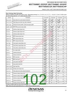
Note: Since the values depend on external clock frequency f(XIN), calculate them by using the bus timing data formulas on the next page.
100

 RENESAS [ RENESAS TECHNOLOGY CORP ]