MULTIJUNCTION TIMERS
10.4 TIO (Input/Output-Related 16-Bit Timer)
10
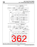
(2) Reload register updates in TIO PWM output mode
In PWM output mode, when the timer remains idle, the reload 0 and reload 1 registers are updated at the
same time data are written to the respective registers. But when the timer is operating, the reload 1 register
is updated by updating the reload 0 register. However, if the reload 0 and reload 1 registers are accessed for
read, the read values are always the data that have been written to the respective registers.
Internal bus
Reload 1
TIOnRL1
Reload 1 WR
Reload 0 WR
Reload 0
TIOnRL0
Buffer
PWM mode control
16-bit counter
TO
Prescaler output
F/F
Figure 10.4.10 PWM Circuit Diagram
To rewrite the reload 0 and reload 1 registers while the timer is operating, rewrite the reload 1 register first
and then the reload 0 register. That way, the reload 0 and reload 1 registers both are updated synchronously
with PWM period, from which the timer starts operating. This operation can normally be performed collec-
tively by accessing 32-bit addresses beginning with the reload 1 register address wordwise. (Data are auto-
matically written to the reload 1 and then the reload 0 registers in succession.)
If the reload 0 and reload 1 registers are updated in the reverse order beginning with reload 0, only the reload
0 register is updated. Note also that if the reload 0 and reload 1 registers are accessed for read, the read
values are always the data that have been written to the respective registers, and not the reload values being
actually used.
When altering PWM period by rewriting the reload registers, if the PWM period terminates before the CPU
finishes writing to reload 0, the PWM period is not altered in the current session and the data written to the
register is reflected in the next period.
(3) Precautions on using TIO PWM output mode
The following describes precautions to be observed when using TIO PWM output mode.
• If the timer is enabled by external input in the same clock period as count is disabled by writing to the
enable bit, the latter has priority so that count is disabled.
• If the counter is accessed for read immediately after being reloaded pursuant to an underflow, the counter
value temporarily reads as H’FFFF but immediately changes to (reload value – 1) at the next clock edge.
• Because the timer operates synchronously with the count clock, a count clock-dependent delay is in-
cluded before F/F output is inverted after the timer is enabled.
32180 Group User’s Manual (Rev.1.0)
10-118

 RENESAS [ RENESAS TECHNOLOGY CORP ]