13.4
Application Notes
1. In master mode, if an instruction to generate a start condition is immediately followed by an
instruction to generate a stop condition, neither condition will be output correctly. To output
consecutive start and stop conditions, after issuing the instruction that generates the start
condition, read the relevant ports, check that SCL and SDA are both low, then issue the
instruction that generates the stop condition.
2. Either of the following two conditions will start the next transfer. Pay attention to these
conditions when reading or writing to ICDR.
Write access to ICDR when ICE = 1 and TRS = 1
Read access to ICDR when ICE = 1 and TRS = 0
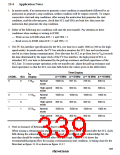
3. The I2C bus interface specification for the SCL rise time tsr is under 1000 ns (300 ns for high-
speed mode). In master mode, the I2C bus interface monitors the SCL line and synchronizes
one bit at a time during communication. If tsr (the time for SCL to go from low to VIH) exceeds
the time determined by the input clock of the I2C bus interface, the high period of SCL is
extended. SCL rise time is determined by the pull-up resistance and load capacitance of the
SCL line. To insure proper operation at the set transfer rate, adjust the pull-up resistance and
load capacitance so that the SCL rise time falls below the values given in the table below.
Time Display
ø = 5 MHz ø = 8 MHz ø = 10 MHz ø = 16 MHz
tcyc
IICX Display
CKDBL
0
0
7.5tcyc
Normal
mode
1000 ns
937 ns
300 ns
1000 ns
300 ns
1000 ns
300 ns
750 ns
300 ns
1000 ns
300 ns
1000 ns
300 ns
486 ns
300 ns
1000 ns
300 ns
1000 ns
300 ns
High-speed 300 ns
mode
0
1
1
1
0
1
17.5tcyc
37.5tcyc
Normal
mode
1000 ns
High-speed 300 ns
mode
Normal
mode
1000 ns
High-speed 300 ns
mode
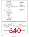
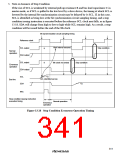
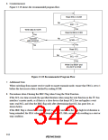
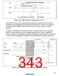
4. Note on Issuance of Retransmission Start Condition
When issuing a retransmission start condition, the condition must be issued after the SCL clock
falls during the acknowledge bit reception period. After the end of the acknowledge bit, the
next data should be written to ICDR after SCL goes high. Figure 13.16 shows the
recommended program flow for issuing a retransmission start condition. A timing chart for the
flowchart in figure 13.16 is shown in figure 13.17.
309

 RENESAS [ RENESAS TECHNOLOGY CORP ]