13.2
Register Descriptions
13.2.1
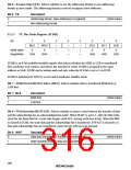
I2C Bus Data Register (ICDR)
Bit
7
ICDR7
—
6
ICDR6
—
5
ICDR5
—
4
ICDR4
—
3
ICDR3
—
2
ICDR2
—
1
ICDR1
—
0
ICDR0
—
Initial value
Read/Write
R/W
R/W
R/W
R/W
R/W
R/W
R/W
R/W
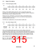
ICDR is an 8-bit readable/writable register that is used as a transmit data register when
transmitting and a receive data register when receiving. Transmitting is started by writing data in
ICDR. Receiving is started by reading data from ICDR.
ICDR is also used as a shift register, so it must not be written or read until data has been
completely transmitted or received. Read or write access while data is being transmitted or
received may result in incorrect data.
The ICDR value is undefined after a reset and in hardware standby mode.
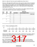
13.2.2
Slave Address Register (SAR)
Bit
7
SVA6
0
6
SVA5
0
5
SVA4
0
4
SVA3
0
3
SVA2
0
2
SVA1
0
1
SVA0
0
0
FS
0
Initial value
Read/Write
R/W
R/W
R/W
R/W
R/W
R/W
R/W
R/W
SAR is an 8-bit readable/writable register that stores the slave address and selects the
communication format. When the chip is in slave mode (and the addressing format is selected), if
the upper 7 bits of SAR match the upper 7 bits of the first byte received after a start condition, the
chip operates as the slave device specified by the master device. SAR is assigned to the same
address as ICMR. SAR can be written and read only when the ICE bit is cleared to 0 in ICCR.
SAR is initialized to H'00 by a reset and in hardware standby mode.
Bits 7 to 1—Slave Address (SVA6 to SVA0): Set a unique address in bits SVA6 to SVA0,
differing from the addresses of other slave devices connected to the I2C bus.
285

 RENESAS [ RENESAS TECHNOLOGY CORP ]