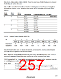
Bits 2to 0— Clock Select (CKS2–CKS0): These bits select one of eight clock sources obtained
by dividing the system clock (ø).
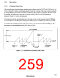
The overflow interval is the time from when the watchdog timer counter begins counting from
H'00 until an overflow occurs. In interval timer mode, WOVF interrupts are requested at this
interval.
Bit 2:
CKS2
Bit 1:
CKS1
Bit 0:
CKS0
Description
øP/2
Overflow Interval (øP = 10 MHz)
0
0
1
0
1
0
1
0
1
0
1
0
1
51.2 µs
819.2 µs
1.6 ms
(Initial value)
øP/32
øP/64
øP/128
øP/256
øP/512
øP/2048
øP/4096
3.3 ms
1
6.6 ms
13.1 ms
52.4 ms
104.9 ms
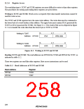
11.2.3
System Control Register (SYSCR)
Bit
7
SSBY
0
6
STS2
0
5
STS1
0
4
3
2
NMIEG
0
1
HIE
0
0
RAME
1
STS0
0
XRST
Initial value
Read/Write
1
R/W
R/W
R/W
R/W
R
R/W
R/W
R/W
Only bit 3 is described here. For details of other bits, see section 3.2., System Control Register
(SYSCR), and descriptions of the relevant modules.
Bit 3—External Reset (XRST): Indicates the reset source. When the watchdog timer is used, a
reset can be generated by watchdog timer overflow as well as by external reset input.
XRST is a read-only bit. It is set to 1 by an external reset and cleared to 0 by an internal reset due
to watchdog timer overflow when the RST/NMI bit is 1.
Bit 3: XRST
Description
0
1
A reset is generated by an internal reset due to watchdog timer overflow
A reset is generated by external reset input
(Initial value)
227

 RENESAS [ RENESAS TECHNOLOGY CORP ]