11.3
Operation
11.3.1
Watchdog Timer Mode
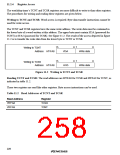
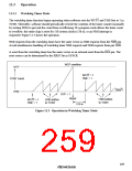
The watchdog timer function begins operating when software sets the WT/IT and TME bits to 1 in
TCSR. Thereafter, software should periodically rewrite the contents of the timer counter (normally
by writing H'00) to prevent the count from overflowing. If a program crash allows the timer count
to overflow, the entire chip is reset for 518 system clocks (518 ø), or an NMI interrupt is
requested. Figure 11.3 shows the operation.
NMI requests from the watchdog timer have the same vector as NMI requests from the NMI pin.
Avoid simultaneous handling of watchdog timer NMI requests and NMI requests from pin NMI.
A reset from the watchdog timer has the same vector as an external reset from the RES pin. The
reset source can be determined by the XRST bit in SYSCR.
WDT overflow
H'FF
WT/IT = 1
TME = 1
TCNT count
H'00
Time t
OVF = 1
Reset
H'00 written
to TCNT
WT/IT = 1
TME = 1
H'00 written
to TCNT
518 ø
Figure 11.3 Operation in Watchdog Timer Mode
229

 RENESAS [ RENESAS TECHNOLOGY CORP ]