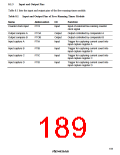
8.1.4
Register Configuration
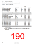
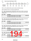
Table 8.2 lists the registers of the free-running timer module.
Table 8.2 Register Configuration
Initial
Value
Name
Abbreviation
TIER
R/W
R/W
R/(W)*1
R/W
R/W
R/W
R/W
R/W
R/W
R
Address
H'FF90
H'FF91
H'FF92
H'FF93
H'FF94*2
H'FF95*2
H'FF96
H'FF97
H'FF98
H'FF99
H'FF9A
H'FF9B
H'FF9C
H'FF9D
H'FF9E
H'FF9F
Timer interrupt enable register
Timer control/status register
Free-running counter (high)
Free-running counter (low)
Output compare register A/B (high) *2
Output compare register A/B (low)*2
Timer control register
H'01
H'00
H'00
H'00
H'FF
H'FF
H'00
H'E0
H'00
H'00
H'00
H'00
H'00
H'00
H'00
H'00
TCSR
FRC (H)
FRC (L)
OCRA/B (H)
OCRA/B (L)
TCR
Timer output compare control register
Input capture register A (high)
Input capture register A (low)
Input capture register B (high)
Input capture register B (low)
Input capture register C (high)
Input capture register C (low)
Input capture register D (high)
Input capture register D (low)
TOCR
ICRA (H)
ICRA (L)
ICRB (H)
ICRB (L)
ICRC (H)
ICRC (L)
ICRD (H)
ICRD (L)
R
R
R
R
R
R
R
Notes: *1 Software can write a 0 to clear bits 7 to 1, but cannot write a 1 in these bits. Bit 0 can be
read and written to.
*2 OCRA and OCRB share the same addresses. Access is controlled by the OCRS
bit in TOCR.
160

 RENESAS [ RENESAS TECHNOLOGY CORP ]