Section 16 Serial Communication Interface 3 (SCI3)
16.6
Multiprocessor Communication Function
Use of the multiprocessor communication function enables data transfer between a number of
processors sharing communication lines by asynchronous serial communication using the
multiprocessor format, in which a multiprocessor bit is added to the transfer data. When
multiprocessor communication is performed, each receiving station is addressed by a unique ID
code. The serial communication cycle consists of two component cycles; an ID transmission cycle
that specifies the receiving station, and a data transmission cycle. The multiprocessor bit is used to
differentiate between the ID transmission cycle and the data transmission cycle. If the
multiprocessor bit is 1, the cycle is an ID transmission cycle; if the multiprocessor bit is 0, the
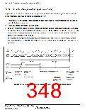
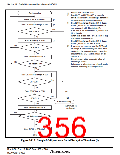
cycle is a data transmission cycle. Figure 16.15 shows an example of inter-processor
communication using the multiprocessor format. The transmitting station first sends the ID code
of the receiving station with which it wants to perform serial communication as data with a 1
multiprocessor bit added. It then sends transmit data as data with a 0 multiprocessor bit added.
When data with a 1 multiprocessor bit is received, the receiving station compares that data with its
own ID. The station whose ID matches then receives the data sent next. Stations whose IDs do not
match continue to skip data until data with a 1 multiprocessor bit is again received.
The SCI3 uses the MPIE bit in SCR3 to implement this function. When the MPIE bit is set to 1,
transfer of receive data from RSR to RDR, error flag detection, and setting the SSR status flags,
RDRF, FER, and OER, to 1, are inhibited until data with a 1 multiprocessor bit is received. On
reception of a receive character with a 1 multiprocessor bit, the MPBR bit in SSR is set to 1 and
the MPIE bit is automatically cleared, thus normal reception is resumed. If the RIE bit in SCR3 is
set to 1 at this time, an RXI interrupt is generated.
When the multiprocessor format is selected, the parity bit setting is rendered invalid. All other bit
settings are the same as those in normal asynchronous mode. The clock used for multiprocessor
communication is the same as that in normal asynchronous mode.
Rev. 3.00 Sep. 10, 2007 Page 318 of 528
REJ09B0216-0300

 RENESAS [ RENESAS TECHNOLOGY CORP ]