Section 16 Serial Communication Interface 3 (SCI3)
16.5.3
Serial Data Transmission
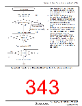
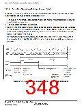
Figure 16.10 shows an example of SCI3 operation for transmission in clock synchronous mode.
In serial transmission, the SCI3 operates as described below.
1. The SCI3 monitors the TDRE flag in SSR, and if the flag is 0, the SCI3 recognizes that data
has been written to TDR, and transfers the data from TDR to TSR.
2. The SCI3 sets the TDRE flag to 1 and starts transmission. If the TIE bit in SCR3 is set to 1 at
this time, a transmit data empty interrupt (TXI) is generated.
3. 8-bit data is sent from the TxD pin synchronized with the output clock when output clock
mode has been specified, and synchronized with the input clock when use of an external clock
has been specified. Serial data is transmitted sequentially from the LSB (bit 0), from the TxD
pin.
4. The SCI3 checks the TDRE flag at the timing for sending the MSB (bit 7).
5. If the TDRE flag is cleared to 0, data is transferred from TDR to TSR, and serial transmission
of the next frame is started.
6. If the TDRE flag is set to 1, the TEND flag in SSR is set to 1, and the TDRE flag maintains
the output state of the last bit. If the TEIE bit in SCR3 is set to 1 at this time, a TEI interrupt
request is generated.
7. The SCK3 pin is fixed high at the end of transmission.
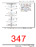
Figure 16.11 shows a sample flow chart for serial data transmission. Even if the TDRE flag is
cleared to 0, transmission will not start while a receive error flag (OER, FER, or PER) is set to 1.
Make sure that the receive error flags are cleared to 0 before starting transmission.
Serial
clock
Serial
data
Bit 0
Bit 1
Bit 7
Bit 0
Bit 1
Bit 6
Bit 7
1 frame
1 frame
TDRE
TEND
LSI
TXI interrupt
TDRE flag
cleared
to 0
TXI interrupt request generated
TEI interrupt request
generated
operation request
generated
User
processing
Data written
to TDR
Figure 16.10 Example of SCI3 Transmission in Clock Synchronous Mode
Rev. 3.00 Sep. 10, 2007 Page 312 of 528
REJ09B0216-0300

 RENESAS [ RENESAS TECHNOLOGY CORP ]