Section 14 Watchdog Timer
Section 14 Watchdog Timer
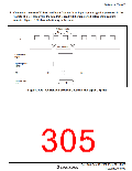
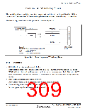
The watchdog timer is an 8-bit timer that can generate an internal reset signal for this LSI if a
system crash prevents the CPU from writing to the timer counter, thus allowing it to overflow.
The block diagram of the watchdog timer is shown in figure 14.1.
CLK
PSS
WDT dedicated
internal oscillator
TCSRWD
TCWD
φ
TMWD
[Legend]
Internal reset
signal
TCSRWD: Timer control/status register WD
TCWD:
PSS:
Timer counter WD
Prescaler S
TMWD:
Timer mode register WD
Figure 14.1 Block Diagram of Watchdog Timer
14.1
Features
•
Selectable from nine counter input clocks.
Eight clock sources (φ/64, φ/128, φ/256, φ/512, φ/1024, φ/2048, φ/4096, and φ/8192) or the
WDT dedicated internal oscillator can be selected as the timer-counter clock. When the WDT
dedicated internal oscillator is selected, it can operate as the watchdog timer in any operating
mode.
•
•
Reset signal generated on counter overflow
An overflow period of 1 to 256 times the selected clock can be set.
The watchdog timer is enabled in the initial state.
It starts operating after the reset state is canceled.
WDT0110A_000020030700
Rev. 3.00 Sep. 10, 2007 Page 275 of 528
REJ09B0216-0300

 RENESAS [ RENESAS TECHNOLOGY CORP ]