Section 13 Timer Z
Complementary PWM mode
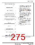
[1] Clear bits STR0 and STR1 in TSTR to 0,
and stop the counter operation of
TCNT_0. Stop TCNT_0 and TCNT_1 and
set complementary PWM mode.
[1]
Stop counter operation
Initialize output pin
[2] Write H'00 to TOCR.
[3] Use bits TPSC2 to TPSC0 in TCR to
select the same counter clock for channels
0 and 1. When an external clock is
selected, select the edge of the external
clock by bits CKEG1 and CKEG0 in TCR.
Do not use bits CCLR1 and CCLR0 in
TCR to clear the counter.
[2]
[3]
Select counter clock
[4] Use bits CMD1 and CMD0 in TFCR to set
complementary PWM mode. FTIOB0 to
FTIOD0 and FTIOA1 to FTIOD1
automatically become PWM output pins.
[5] Set H'00 to TOCR.
Set complementary
PWM mode
[4]
[5]
[6] TCNT_1 must be H'0000. Set a non-
overlapped period to TCNT_0.
Initialize output pin
[7] GRA_0 is a cycle register. Set the cycle to
GRA_0. Set the timing to change the
PWM output waveform to GRB_0, GRA_1,
and GRB_1. Note that the timing must be
set within the range of compare match
carried out for TCNT_0 and TCNT_1.
For GR settings, see 3. Setting GR Value
in Complementary PWM Mode in section
13.4.7, Complementary PWM Mode.
[8] Use TOER to enable or disable the timer
output.
[6]
[7]
Set TCNT
Set GR
[8]
[9]
Enable waveform output
[9] Set the STR0 and STR1 bits in TSTR to 1
to start the count operation.
Start counter operation
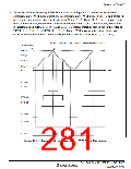
<Complementary PWM mode>
Note: To re-enter complementary PWM mode, first, enter a mode other than the complementary
PWM mode. After that, repeat the setting procedures from step [1].
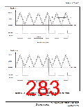
For settings of waveform outputs with a duty cycle of 0% and 100%, see the settings shown
in 2. Examples of Complementary PWM Mode Operation and 3. Setting GR Value in
Complementary PWM Mode in section 13.4.7, Complementary PWM Mode.
Figure 13.29 Example of Complementary PWM Mode Setting Procedure
Rev. 3.00 Sep. 10, 2007 Page 245 of 528
REJ09B0216-0300

 RENESAS [ RENESAS TECHNOLOGY CORP ]