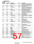
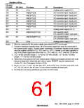
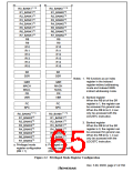
Number of Pins
FP-208C
FP-208E
BP-240A
Pin Name
I/O
Description
198
B6
AVss
—
Analog power supply (0 V)
199
A6
AN[0]/PTL[0]
AN[1]/PTL[1]
AN[2]/PTL[2]
AN[3]/PTL[3]
AN[4]/PTL[4]
AN[5]/PTL[5]
AVcc
I
A/D converter input / input port L
A/D converter input / input port L
A/D converter input / input port L
A/D converter input / input port L
A/D converter input / input port L
A/D converter input / input port L
Analog power supply (3.3 V)
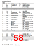
200
D5
I
201
C5
I
202
D4
I
203
A5
I
204
C4
I
205
A4
—
I
206
B5
AN[6]/DA[1]/PTL[6]
A/D converter input /
D/A converter output / input port L
207
208
B3
B4
AN[7]/DA[0]/PTL[7]
AVss
I
A/D converter input /
D/A converter output / input port L
—
Analog power supply (0 V)
Notes: 1. Must be connected to the power supply even when the RTC is not used.
2. Except in hardware standby mode, all of the power supply pins must be connected to
the system power supply. (Supply power constantly.) In hardware standby mode, power
must be supplied at least to VCC –RTC and VSS –RTC. If power is not being supplied to
any of the power supply pins other than VCC –RTC and VSS –RTC, hold the CA pin low.
3. 2.0 V for the 200 MHz model, 1.9 V for the 167 MHz model, 1.8 V for the 133 MHz
model, 1.7 V for the 100 MHz model.
4. When this LSI is used on the user system alone, without an emulator and the UDI, hold
this pin at high level. When this pin is low or open, RESETP may be masked (see
section 22, User Debugging Interface (UDI)).
5. B2, B1, C1, U1, V1, W1, V2, W2, W3, W17, W18, W19, V18, V19, B19, A19, B18, A18,
A17, A3, A2, and A1 are NC pins. Do not connect anything to these pins.
6. If EXTAL2 is not used, pull this pin up to the Vcc-RTC level.
Rev. 5.00, 09/03, page 17 of 760

 RENESAS [ RENESAS TECHNOLOGY CORP ]