11.1.2
Block Diagram
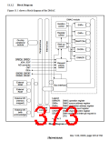
Figure 11.1 shows a block diagram of the DMAC.
DMAC module
Iteration
control
SARn
Register
control
DARn
DMATCRn
CHCRn
On-chip
peripheral
module
Start-up
control
DMAOR
DREQ0, DREQ1
IrDA, SCIF
A/D converter
CMT
Request
priority
control
DEIn
DACK0, DACK1
DRAK0, DRAK1
External
ROM
Bus interface
External
RAM
Legend
DMAOR: DMAC operation register
External I/O
(memory
mapped)
SARn:
DARn:
DMAC source address register
DMAC destination address register
Bus state
controller
DMATCRn:DMAC transfer count register
External I/O
(with
acknowledge)
CHCRn:
DEIn:
DMAC channel control register
DMA transfer-end interrupt request to
CPU
n = 0 to 3
Figure 11.1 Block Diagram of DMAC
Rev. 5.00, 09/03, page 329 of 760

 RENESAS [ RENESAS TECHNOLOGY CORP ]