8.5
Module Standby Function
8.5.1
Transition to Module Standby Function
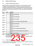
Setting the standby control register MSTP8–MSTP0 bits to 1 halts the supply of clocks to the
corresponding on-chip peripheral modules. This function can be used to reduce the power
consumption in normal mode and sleep mode. The module standby function holds the state prior
to halting the external pins of the on-chip peripheral modules. TMU external pins hold their state
prior to the halt. SCI external pins go to the reset state. With a few exceptions, all registers hold
their values.
Bit
Value
Description
MSTP8
0
1
0
1
0
1
0
1
0
1
0
1
0
1
0
1
0
1
UBC runs
Supply of clock to UBC halted
DMAC runs
MSTP7
MSTP6
MSTP5
MSTP4
MSTP3
MSTP2
MSTP1
MSTP0
Supply of clock to DMAC halted
DAC runs
Supply of clock to DAC halted
ADC runs
Supply of clock to ADC halted, and all registers initialized
SCIF runs
Supply of clock to SCIF halted
IrDA runs
Supply of clock to IrDA halted
TMU runs
1
*
Supply of clock to TMU halted. Registers initialized
RTC runs
*2*3
Supply of clock to RTC halted. Register access prohibited
SCI runs
Supply of clock to SCI halted
Notes: 1. The registers initialized are the same as in standby mode (see table 8.4).
2. The counter runs.
3. Before switching the RTC to module standby, access at least one among the registers
RTC, SCI, and TMU.
8.5.2
Clearing Module Standby Function
The module standby function can be cleared by clearing the MSTPSLP0 and MSTP8–MSTP0 bits
to 0, or by a power-on reset or manual reset.
Rev. 5.00, 09/03, page 191 of 760

 RENESAS [ RENESAS TECHNOLOGY CORP ]