7.2.9
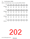
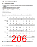
Break Control Register (BRCR)
BRCR sets the following conditions:
1. Channels A and B are used in two independent channels condition or under the sequential
condition.
2. A break is set before or after instruction execution.
3. A break is set by the number of execution times.
4. Determine whether to include data bus on channel B in comparison conditions.
5. Enable PC trace.
6. Enable the ASID check.
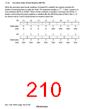
The break control register (BRCR) is a 32-bit read/write register that has break conditions match
flags and bits for setting a variety of break conditions. A power-on reset initializes BRCR to
H'00000000.
Bit:
31
—
0
30
—
0
29
—
0
28
—
0
27
—
0
26
—
0
25
—
0
24
—
0
Initial value:
R/W:
R
R
R
R
R
R
R
R
Bit:
23
—
0
22
—
0
21
20
19
—
0
18
—
0
17
—
0
16
—
0
BASMA BASMB
Initial value:
R/W:
0
0
R
R
R/W
R/W
R
R
R
R
Bit:
15
14
13
12
11
10
PCBA
0
9
—
0
8
—
0
SCMFCA SCMFCB SCMFDA SCMFDB PCTE
Initial value:
R/W:
0
0
0
0
0
R/W
R/W
R/W
R/W
R/W
R/W
R
R
Bit:
7
DBEB
0
6
PCBB
0
5
—
0
4
—
0
3
2
—
0
1
—
0
0
ETBE
0
SEQ
0
Initial value:
R/W:
R/W
R/W
R
R
R/W
R
R
R/W
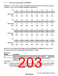
Bits 31 to 22—Reserved: These bits are always read as 0. The write value should always be 0.
Rev. 5.00, 09/03, page 162 of 760

 RENESAS [ RENESAS TECHNOLOGY CORP ]