3.1.3
SH7709S MMU
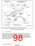
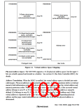
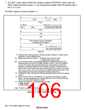
Virtual Address Space: The SH7709S uses 32-bit virtual addresses to access a 4-Gbyte virtual
address space that is divided into several areas. Address space mapping is shown in figure 3.2.
•
Privileged Mode
In privileged mode, there are five areas, P0–P4. The P0 and P3 areas are mapped onto physical
address space in page units, in accordance with address translation table information. Write-
back or write-through can be selected for write access by means of a cache control register
(CCR) setting.
Mapping of the P1 area is fixed in physical address space (H'00000000 to H'1FFFFFFF). In
the P1 area, setting a virtual address MSB (bit 31) to 0 generates the corresponding physical
address. P1 area accesses can be cached, and the cache control register (CCR) is set to indicate
whether to cache or not. Write-back or write-through mode can be selected.
Mapping of the P2 area is fixed in physical address space (H'00000000 to H'1FFFFFFF). In the
P2 area, setting the top three virtual address bits (bits 31, 30, and 29) to 0 generates the
corresponding physical address. P2 area access cannot be cached.
The P1 and P2 areas are not mapped by the address translation table, so the TLB is not used
and no exceptions such as TLB misses occur. Initialization of MMU control registers,
exception handling routines, and the like should be located in the P1 and P2 areas. Routines
that require high-speed processing should be placed in the P1 area, since it can be cached.
Some peripheral module control registers are located in area 1 of the physical address space.
When the physical address space is not used for address translation, these registers should be
located in the P2 area. When address translation is to be used, set no caching.
The P4 area is used for mapping peripheral module register addresses, etc.
•
User Mode
In user mode, 2 Gbytes of the virtual address space from H'00000000 to H'7FFFFFFF (area
U0) can be accessed. U0 is mapped onto physical address space in page units, in accordance
with address translation table information.
Rev. 5.00, 09/03, page 58 of 760

 RENESAS [ RENESAS TECHNOLOGY CORP ]