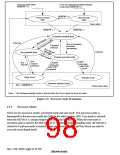
From any state when
RESETP = 0
From any state but hardware standby
mode when RESETM = 0
RESETP = 0
Power-on reset
state
Manual reset
state
Reset state
RESETP = 1
RESETM = 1
Exception-handling state
Interrupt
End of exception
transition
processing
Exception
interrupt
Interrupt
Bus-released state
Program execution state
Bus
Bus
request
SLEEP
SLEEP
request
clearance
instruction
with STBY
bit set
instruction
with STBY
bit cleared
Sleep mode
Standby mode
Hardware standby mode*
CA = 1,RESETP=0
Power-down state
Note: * The hardware standby mode is entered when the CA pin goes low from any state.
Figure 2.8 Processor State Transitions
2.5.2
Processor Modes
There are two processor modes: privileged mode and user mode. The processor mode is
determined by the processor mode bit (MD) in the status register (SR). User mode is selected
when the MD bit is 0, and privileged mode when the MD bit is 1. When the reset state or
exception state is entered, the MD bit is set to 1. When exception handling ends, the MD bit is
cleared to 0 and user mode is entered. There are certain registers and bits which can only be
accessed in privileged mode.
Rev. 5.00, 09/03, page 54 of 760

 RENESAS [ RENESAS TECHNOLOGY CORP ]