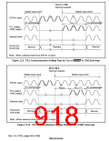
CKIO
tBREQH
tBREQS
tBREQH
tBREQS
tBACKD
tBACKD
tBOFF1
tBON1
A[25-0],
,
,
RD/
RD/
,
,
,
,
,
,
,
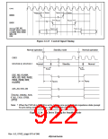
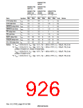
Figure 22.13 Control Signal Timing
Normal operation
Standby mode
Normal operation
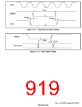
CKIO
STATUS 0, STATUS 1
Normal
Standby
Normal
tSTD2
tSTD1
,
, RD/
,
,
,
,
,
,
,
,
tBON2
tBOFF2
RD/
A25–A0, D63–D0
DACKn, DRAKn, SCK,
TXD, TXD2,
,
*
Note: * When the PHZ bit in STBCR is set to 1, these pins go to the high-impedance state (except
for pins being used as port pins, which retain their port state).
Figure 22.14 Pin Drive Timing for Standby Mode
Rev. 6.0, 07/02, page 870 of 986

 RENESAS [ RENESAS TECHNOLOGY CORP ]