Start
bit
Data
Parity Stop Start
Data
Parity Stop
1
bit
bit bit
bit
bit
Serial
data
0
D0
D1
D7 0/1
1
0
D0 D1
D7 0/1
0
0/1
RDF
FER
RXI interrupt
request
Data read and RDF flag
read as 1 then cleared to
0 by RXI interrupt handler
ERI interrupt request
generated by receive
error
One frame
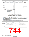
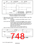
Figure 16.11 Example of SCIF Receive Operation
(Example with 8-Bit Data, Parity, One Stop Bit)
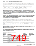
5. When modem control is enabled, the 5765 signal is output when SCFRDR2 is empty. When
5765 is 0, reception is possible.
SH7750:
When 5765 is 1, this indicates that SCFRDR2 contains 15 or more
bytes of data.
SH7750S, SH7750R: When 5765 is 1, this indicates that SCFRDR2 contains a number of
data bytes equal to or greater than the 5765 output active trigger set
number. The 5765 output active trigger value is specified by bits 10 to
8 in the FIFO control register (SCFCR2), described in section 16.2.9,
FIFO control register (SCFCR2).
5765 also becomes 1 when bit 4 (RE) in SCSCR2 is 0.
Figure 16.12 shows an example of the operation when modem control is used.
Start
bit
Parity Stop
Start
bit
bit
bit
Serial data
RxD2
0
D0 D1 D2
D7 0/1
1
0
Figure 16.12 Example of Operation Using Modem Control (5765)
Rev. 6.0, 07/02, page 696 of 986

 RENESAS [ RENESAS TECHNOLOGY CORP ]