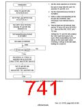
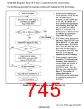
Serial Data Reception: Figure 16.10 shows a sample flowchart for serial reception.
Use the following procedure for serial data reception after enabling the SCIF for reception.
Start of reception
1. Receive error handling and
break detection: Read the DR,
ER, and BRK flags in
SCFSR2, and the ORER flag
in SCLSR2, to identify any
error, perform the appropriate
error handling, then clear the
DR, ER, BRK, and ORER
flags to 0. In the case of a
framing error, a break can also
be detected by reading the
value of the RxD2 pin.
Read ER, DR, BRK flags in
SCFSR2 and ORER
flag in SCLSR2
Yes
ER or DR or BRK or ORER
= 1?
Error handling
No
2. SCIF status check and receive
data read : Read SCFSR2 and
check that RDF = 1, then read
the receive data in SCFRDR2,
read 1 from the RDF flag, and
then clear the RDF flag to 0.
The transition of the RDF flag
from 0 to 1 can also be
Read RDF flag in SCFSR2
No
RDF = 1?
Yes
identified by an RXI interrupt.
Read receive data in
SCFRDR2, and clear RDF
flag in SCFSR2 to 0
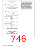
3. Serial reception continuation
procedure: To continue serial
reception, read at least the
receive trigger set number of
receive data bytes from
SCFRDR2, read 1 from the
RDF flag, then clear the RDF
flag to 0. The number of
receive data bytes in
No
All data received?
Yes
Clear RE bit in SCSCR2 to 0
SCFRDR2 can be ascertained
by reading the lower bits of
SCFDR2.
End of reception
Figure 16.10 Sample Serial Reception Flowchart (1)
Rev. 6.0, 07/02, page 693 of 986

 RENESAS [ RENESAS TECHNOLOGY CORP ]