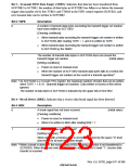
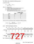
The SCBRR2 setting is found from the following equation.
Asynchronous mode:
P
φ
N =
× 106 – 1
64 × 22n–1 × B
Where B: Bit rate (bits/s)
N: SCBRR2 setting for baud rate generator (0 ≤ N ≤ 255)
Pφ: Peripheral module operating frequency (MHz)
n: Baud rate generator input clock (n = 0 to 3)
(See the table below for the relation between n and the clock.)
SCSMR2 Setting
n
0
1
2
3
Clock
Pφ
CKS1
CKS0
0
0
1
1
0
1
0
1
Pφ/4
Pφ/16
Pφ/64
The bit rate error in asynchronous mode is found from the following equation:
P
× 106
φ
Error (%) =
– 1 × 100
(N + 1) × B × 64 × 22n–1
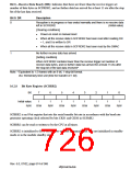
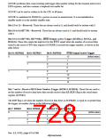
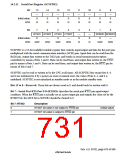
16.2.9 FIFO Control Register (SCFCR2)
Bit:
15
—
0
14
—
0
13
—
0
12
—
0
11
—
0
10
9
8
RSTRG2* RSTRG1* RSTRG0*
Initial value:
R/W:
0
0
0
R
R
R
R
R
R/W
R/W
R/W
Bit:
7
6
5
4
3
MCE
0
2
1
0
LOOP
0
RTRG1 RTRG0 TTRG1 TTRG0
TFRST RFRST
Initial value:
R/W:
0
0
0
0
0
0
R/W
R/W
R/W
R/W
R/W
R/W
R/W
R/W
Note: * Reserved bit in the SH7750.
Rev. 6.0, 07/02, page 675 of 986

 RENESAS [ RENESAS TECHNOLOGY CORP ]