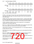
16.2.7 Serial Status Register (SCFSR2)
Bit:
15
PER3
0
14
PER2
0
13
PER1
0
12
PER0
0
11
FER3
0
10
FER2
0
9
FER1
0
8
FER0
0
Initial value:
R/W:
R
R
R
R
R
R
R
R
Bit:
7
ER
0
6
TEND
1
5
TDFE
1
4
BRK
0
3
FER
0
2
PER
0
1
RDF
0
0
DR
0
Initial value:
R/W: R/(W)* R/(W)* R/(W)* R/(W)*
Note: * Only 0 can be written, to clear the flag.
R
R
R/(W)* R/(W)*
SCFSR2 is a 16-bit register. The lower 8 bits consist of status flags that indicate the operating
status of the SCIF, and the upper 8 bits indicate the number of receive errors in the data in the
receive FIFO register.
SCFSR2 can be read or written to by the CPU at all times. However, 1 cannot be written to flags
ER, TEND, TDFE, BRK, RDF, and DR. Also note that in order to clear these flags they must be
read as 1 beforehand. The FER flag and PER flag are read-only flags and cannot be modified.
SCFSR2 is initialized to H'0060 by a power-on reset or manual reset. It is not initialized in
standby mode or in the module standby state.
Bits 15 to 12—Number of Parity Errors (PER3–PER0): These bits indicate the number of data
bytes in which a parity error occurred in the receive data stored in SCFRDR2.
After the ER bit in SCFSR2 is set, the value indicated by bits 15 to 12 is the number of data bytes
in which a parity error occurred.
If all 16 bytes of receive data in SCFRDR2 have parity errors, the value indicated by bits PER3 to
PER0 will be 0.
Bits 11 to 8—Number of Framing Errors (FER3–FER0): These bits indicate the number of
data bytes in which a framing error occurred in the receive data stored in SCFRDR2.
After the ER bit in SCFSR2 is set, the value indicated by bits 11 to 8 is the number of data bytes in
which a framing error occurred.
If all 16 bytes of receive data in SCFRDR2 have framing errors, the value indicated by bits FER3
to FER0 will be 0.
Rev. 6.0, 07/02, page 668 of 986

 RENESAS [ RENESAS TECHNOLOGY CORP ]