•
•
•
•
•
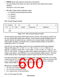
011: Quadword size (64-bit) specification
100: 32-byte block transfer specification
101: Setting prohibited
110: Request queue clear specification
111: Transfer end specification
Bit 60: Read/Write (R/W)
•
0: Memory read specification
•
1: Memory write specification
Bits 59 and 58: Channel Number (ID1, ID0)
•
•
•
•
00: Channel 0 (demand data transfer)
01: Channel 1
10: Channel 2
11: Channel 3
Bits 57 and 56: Transfer Request Mode (MD1, MD0)
•
•
•
•
00: Handshake protocol (data bus used)
01: Burst mode (edge detection) specification
10: Burst mode (level detection) specification
11: Cycle steal mode specification
Bits 55 to 48: Transfer Count (COUNT7–COUNT0)
•
Transfer count: 1 to 255
•
00000000: Maximum number of transfers (16M)
Bits 47 to 32: Reserved
Bits 31 to 0: Address (ADDRESS31–ADDRESS0)
•
R/W = 0: Transfer source address specification
•
R/W = 1: Transfer destination address specification
Notes: 1. Only the ID field is valid for channels 1 to 3.
2. To start DMA transfer by means of demand data transfer on channel 0, the initial value
of MD in the DTR format must be 01, 10, or 11.
3. The COUNT field is ignored if MD = 00.
4. In edge-sense burst mode, DMA transfer is executed continuously. In level-sense burst
mode and cycle steal mode, a handshake protocol is used to transfer each unit of data.
5. The maximum number of transfers can be specified by setting COUNT = 0 as DTR
format initialization data. If the amount of data to be transferred is unknown, set
COUNT = 0, start DMA transfer, and transfer the DTR format (ID = 00, MD ≠ 00, SZ
Rev. 6.0, 07/02, page 549 of 986

 RENESAS [ RENESAS TECHNOLOGY CORP ]