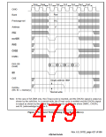
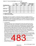
Table 13.17 Cycles for which Pipeline Access is Possible
Succeeding Access
DMAC Dual
CPU
Write
DMAC Single
Preceding Access
Read
X
Read
Write
Read
Write
O
CPU
Read
X
X
X
O
O
O
O
O
X
X
X
X
X
X
X
O
O
X
Write
Read
Write
Read
Write
X
O
DMAC dual
DMAC single
X
X
O
O
X
O
O
O
O
O
O
O
O
O
O: Pipeline access possible
X: Pipeline access not possible
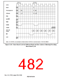
Refreshing: The bus state controller is provided with a function for controlling synchronous
DRAM refreshing. Auto-refreshing can be performed by clearing the RMODE bit to 0 and setting
the RFSH bit to 1 in MCR. If synchronous DRAM is not accessed for a long period, self-refresh
mode, in which the power consumption for data retention is low, can be activated by setting both
the RMODE bit and the RFSH bit to 1.
•
Auto-Refreshing
Refreshing is performed at intervals determined by the input clock selected by bits CKS2–
CKS0 in RTCSR, and the value set in RTCOR. The value of bits CKS2–CKS0 in RTCOR
should be set so as to satisfy the refresh interval specification for the synchronous DRAM
used. First make the settings for RTCOR, RTCNT, and the RMODE and RFSH bits in MCR,
then make the CKS2–CKS0 setting last of all. When the clock is selected by CKS2–CKS0,
RTCNT starts counting up from the value at that time. The RTCNT value is constantly
compared with the RTCOR value, and if the two values are the same, a refresh request is
generated and an auto-refresh is performed. At the same time, RTCNT is cleared to zero and
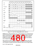
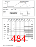
the count-up is restarted. Figure 13.40 shows the auto-refresh cycle timing.
First, an REF command is issued in the TRr cycle. After the TRr cycle, new command output
cannot be performed for the duration of the number of cycles specified by bits TRAS2–TRAS0
in MCR plus the number of cycles specified by bits TRC2–TRC0 in MCR. The TRAS2–
TRAS0 and TRC2–TRC0 bits must be set so as to satisfy the synchronous DRAM refresh
cycle time specification (active/active command delay time).
Auto-refreshing is performed in normal operation, in sleep mode, and in the case of a manual
reset.
When both areas 2 and 3 are set to the synchronous DRAM, auto-refreshing of area 2 is
performed subsequent to area 3.
Rev. 6.0, 07/02, page 431 of 986

 RENESAS [ RENESAS TECHNOLOGY CORP ]