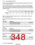
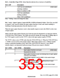
2. Channel 2 TCR bit configuration
Bit:
15
—
0
14
—
0
13
—
0
12
—
0
11
—
0
10
—
0
9
ICPF
0
8
UNF
0
Initial value:
R/W:
R
R
R
R
R
R
R/W
R/W
Bit:
7
ICPE1
0
6
ICPE0
0
5
UNIE
0
4
3
2
1
0
CKEG1 CKEG0 TPSC2 TPSC1 TPSC0
Initial value:
R/W:
0
0
0
0
0
R/W
R/W
R/W
R/W
R/W
R/W
R/W
R/W
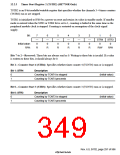
3. TCR bit configuration for channels 3 and 4 (SH7750R only)
Bit:
15
—
0
14
—
0
13
—
0
12
—
0
11
—
0
10
—
0
9
—
0
8
UNF
0
Initial value:
R/W:
R
R
R
R
R
R
R
R/W
Bit:
7
—
0
6
—
0
5
UNIE
0
4
—
0
3
—
0
2
1
0
TPSC2 TPSC1 TPSC0
Initial value:
R/W:
0
0
0
R
R
R/W
R
R
R/W
R/W
R/W
Bits 15 to 9, 7, and 6 (Channels 0 and 1); Bits 15 to 10 (Channel 2)—Reserved: These bits are
always read as 0. A write to these bits is invalid, but the write value should always be 0.
Bit 9—Input Capture Interrupt Flag (ICPF) (Channel 2 Only): Status flag, provided in
channel 2 only, that indicates the occurrence of input capture.
Bit 9: ICPF
Description
0
Input capture has not occurred
[Clearing condition]
(Initial value)
When 0 is written to ICPF
Input capture has occurred
[Setting condition]
1
When input capture occurs*
Note: * Writing 1 does not change the value.
Rev. 6.0, 07/02, page 300 of 986

 RENESAS [ RENESAS TECHNOLOGY CORP ]