NESG3033M14
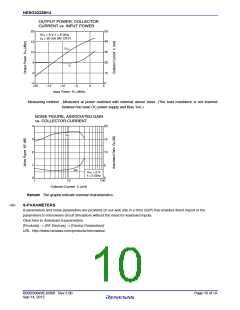
OUTPUT POWER, COLLECTOR
CURRENT vs. INPUT POWER
20
15
10
5
50
40
30
20
10
0
V
CE = 3 V, f = 2 GHz
Icq = 20 mA (RF OFF)
P
out
I
C
0
–5
–20
–15
–10
–5
0
5
Input Power Pin (dBm)
Measuring method : Measured at power matched with external sleeve tuner. (The load resistance is not inserted
between the base DC power supply and Bias Tee.)
NOISE FIGURE, ASSOCIATED GAIN
vs. COLLECTOR CURRENT
4
3
2
1
0
20
15
10
G
a
5
0
NF
V
CE = 2 V
f = 2 GHz
1
10
Collector Current I
100
C
(mA)
Remark The graphs indicate nominal characteristics.
<R>
S-PARAMETERS
S-parameters and noise parameters are provided on our web site in a form (S2P) that enables direct import of the
parameters to microwave circuit simulators without the need for keyboard inputs.
Click here to download S-parameters.
[Products] → [RF Devices] → [Device Parameters]
URL http://www.renesas.com/products/microwave/
R09DS0049EJ0300 Rev.3.00
Sep 14, 2012
Page 10 of 14

 RENESAS [ RENESAS TECHNOLOGY CORP ]